
Method for protection switching in ethernet ring network

a protection switching and ethernet ring network technology, applied in data switching networks, frequency-division multiplexes, instruments, etc., can solve problems such as inability to provide prompt protection switching, etc., and achieve the effects of reducing network bandwidth, protecting switching, and large bandwidth

Inactive Publication Date: 2010-05-06
ELECTRONICS & TELECOMM RES INST +1
View PDF4 Cites 58 Cited by
  • Summary
  • Abstract
  • Description
  • Claims
  • Application Information

AI Technical Summary

Benefits of technology

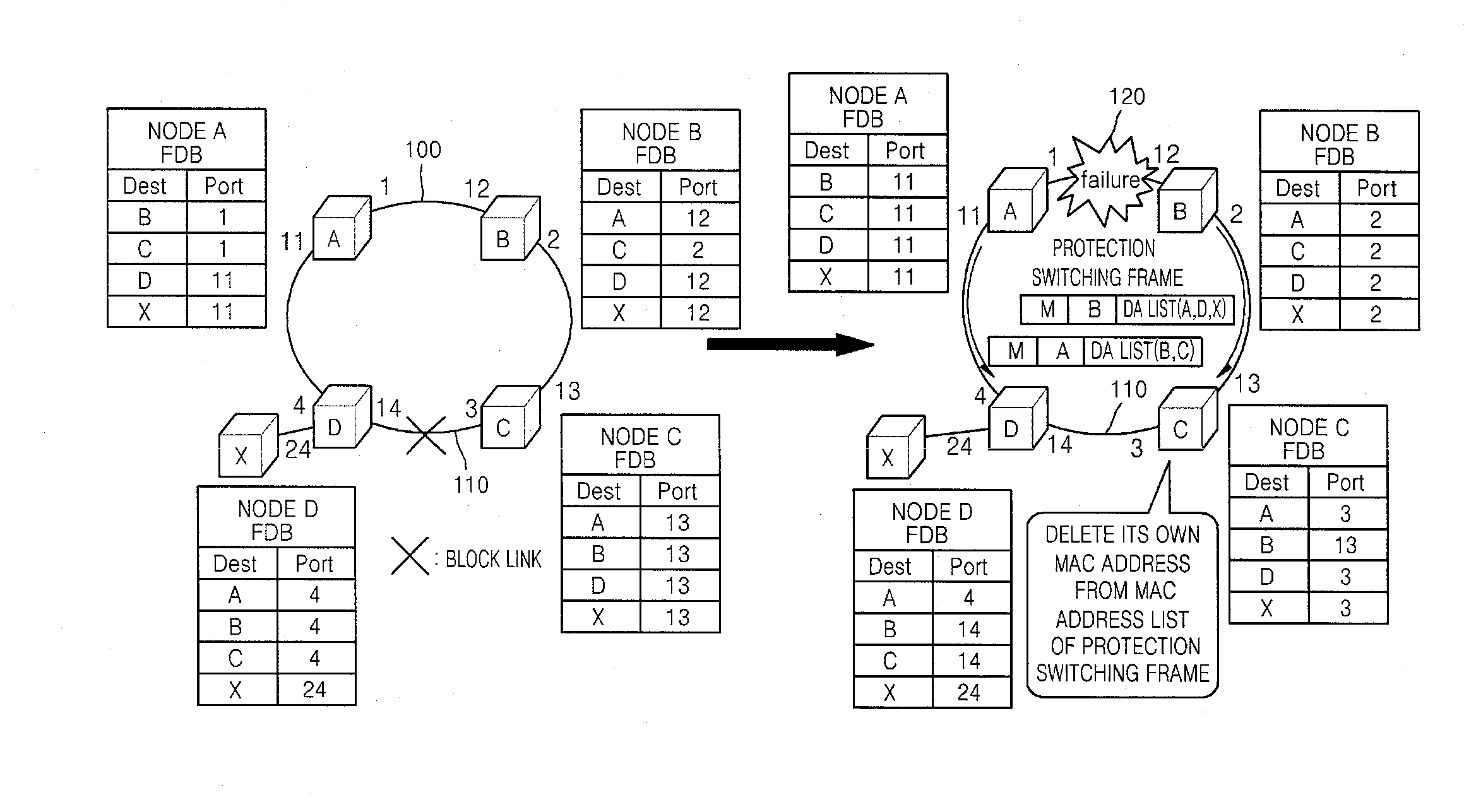
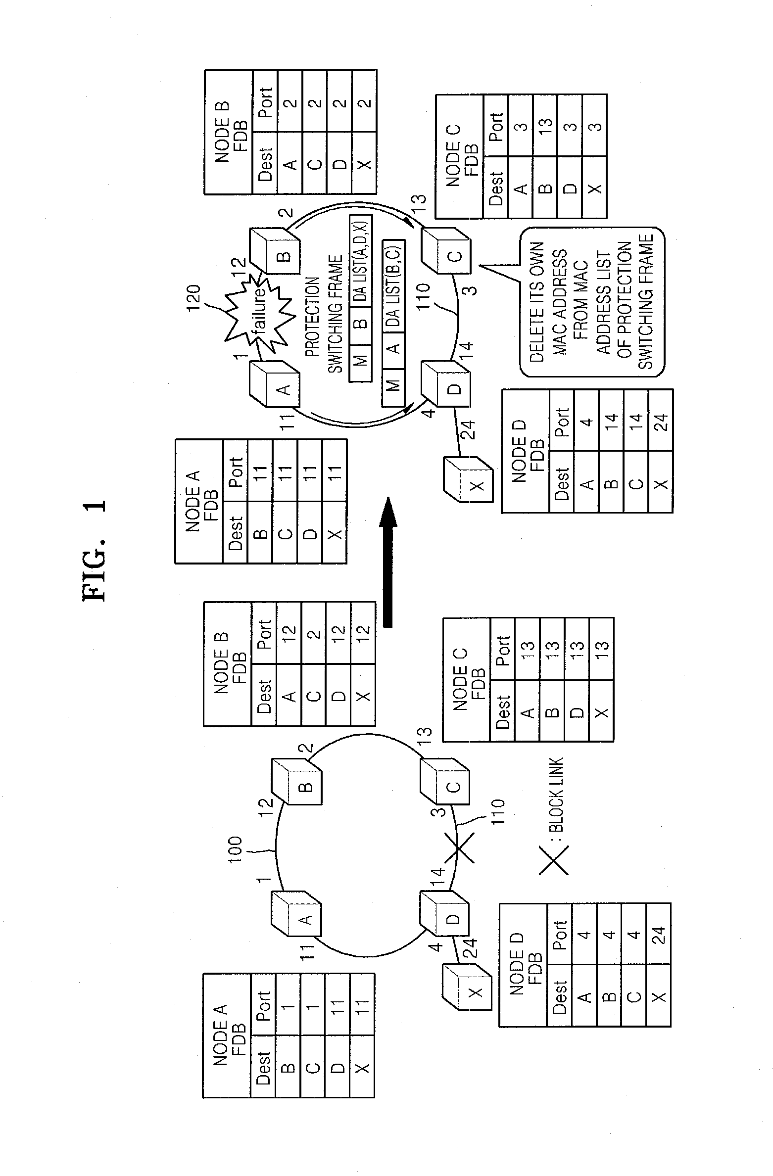
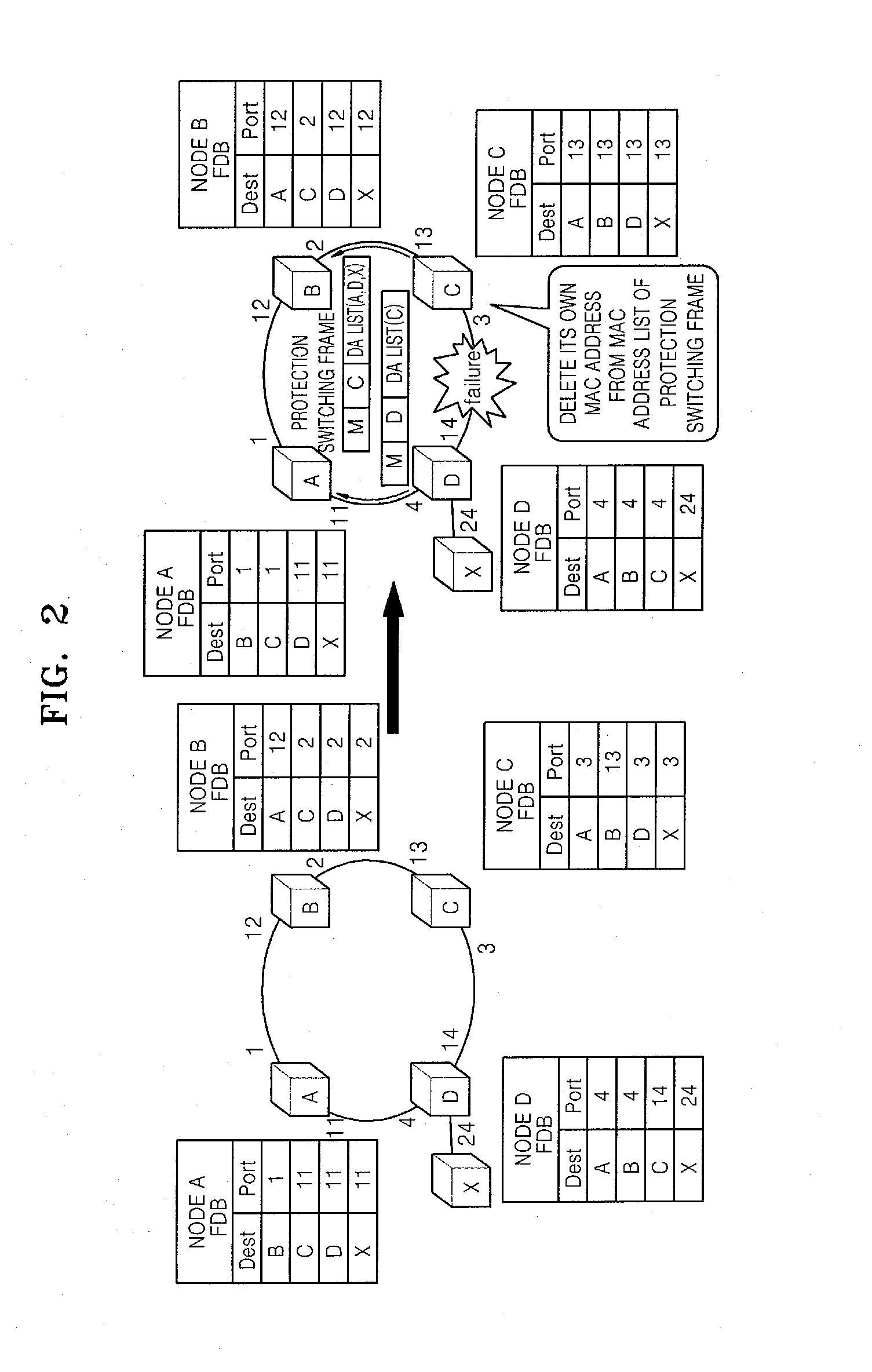
[0018]According to the present invention, quick protection switching is provided in an Ethernet ring network, and an overshoot transition phenomenon that occurs after the protection switching is reduced by using a protection switching frame that does not require large bandwidth and is effective. Also, by reducing a network bandwidth and unnecessary usage of a buffer, resources and expenses can be reduced.
[0019]Also, by using a block bridge using first and second share nodes in an Ethernet multi-ring network, protection switching within 50 ms can be effectively provided without a conventional overshoot transition phenomenon.

Problems solved by technology

When a physical block link due to a failure and a block link for loop prevention are newly selected, a forwarding table is no longer valid, and thus all nodes require new forwarding tables.
In order to prevent a packet loss due to such transmission phenomenon, the link amount of the ring network or the bandwidth of the ring network should be obtained more than necessary, which is inefficient.
However in this case, prompt protection switching (protection switching within 50 ms generally required in a real time voice communication centered network) cannot be provided.

Method used


Image

  • Method for protection switching in ethernet ring network
  • Method for protection switching in ethernet ring network
  • Method for protection switching in ethernet ring network

Examples


Embodiment Construction

Technical Problem

[0010]The present invention provides a protection switching method which solves a problem of an ineffective protection switching technology in an Ethernet ring network, and settles a transition phenomenon where the traffic amount overshoots after protection switching.

[0011]The present invention also provides an effective protection switching method which uses a share node in an Ethernet multi-ring network.

Technical Solution

[0012]According to an aspect of the present invention, there is provided a protection switching method of a node connected to a link having a failure in a ring network, the protection switching method including: generating a protection switching frame including an address list of a forwarding table corresponding to a port connected to the link; and transmitting the protection switching frame.

[0013]According to another aspect of the present invention, there is provided a protection switching method of a node receiving a protection switching frame i...


PUM


Abstract

Provided is a protection switching method via forwarding table correction in an Ethernet ring network. Upon detecting a failure in a link, a node generates a protection switching frame including an address list of a forwarding table corresponding to a port connected to the link, and transmits the protection switching frame to a port at an opposite direction of the link. A node that receives the protection switching frame deletes its own address from the address list included in the protection switching frame, and changes a port number of an address in the address list of the protection switching frame from among addresses of the forwarding table corresponding to a port that received the protection switching frame to a port number in an opposite direction of the port that received the protection switching frame or deletes the port number of the address in the address list.

Description

TECHNICAL FIELD[0001]The present invention relates to a protection switching method in an Ethernet ring network, and more particularly, to a protection switching method via transmission table correction of an Ethernet ring node.[0002]The present invention is derived from a research project supported by the Information Technology (IT) Research & Development (R&D) program of the Ministry of Information and Communication (MIC) and the Institute for Information Technology Advancement (IITA) [2005-S-102-03, Carrier Class Ethernet Technology].BACKGROUND ART[0003]In order to provide Ethernet ring protection switching, a forwarding table is prepared so that frame forwarding of each Ethernet node does not form an endless loop in an Ethernet ring. Such forwarding table is realized via a link blocking method and an active management method.[0004]According to the link blocking method, a link included in a ring is deactivated so as to logically prevent the ring from forming as if the link does n...

Claims


Application Information

Patent Timeline
IPC IPC(8): G06F11/00H04L12/26
CPCH04L12/42H04L12/4625H04L12/4641H04L41/0668
Inventor RYOO, JEONG-DONGRHEE, JUNE-KOOIM, JIN-SUNGJOO, BHEOM-SOONKIM, YOUNG-SUNAHMAD, ZAHIR UDDIN
Owner ELECTRONICS & TELECOMM RES INST
Learn More