Fuel bottle for a fuel cartridge using the same.

a technology of fuel bottles and fuel cartridges, applied in the direction of transportation and packaging, other domestic articles, electrochemical generators, etc., can solve the problems of insufficient shape, capacity and formability of the inside container, and achieve the effect of improving the strength of the bottl

Inactive Publication Date: 2010-05-06
TOYO SEIKAN KAISHA LTD +1
View PDF1 Cites 2 Cited by
  • Summary
  • Abstract
  • Description
  • Claims
  • Application Information

AI Technical Summary

Benefits of technology

[0006]In view of such problems of the prior art, it is an object of the invention to provide a fuel bottle for a fuel cell which can be housed efficiently in a hard case and can also secure necessary capacity and formability as well as a fuel cartridge using this fuel bottle.
[0026]According to this fuel cartridge for a fuel cell, the fuel cartridge comprises a hard case provided with a push button and a rib formed on an inside surface of the hard case which can house a fuel bottle as defined in the fifth aspect in such a manner that the pinch portion and the portion in the vicinity of such pinch portion, or the pinch portion or the portion in the vicinity of such pinch portion of the fuel body is pressed by the rib and the outwardly protruding pinch portion or the portion in the vicinity of such pinch portion, or the pinch portion which is bent toward the bottle main body or the portion in the vicinity of such pinch portion is clamped by the rib of the hard case and, therefore, the bottle is housed in such a manner that deformation of the bottle can be prevented and deformation and opening of the pinch portion can thereby be prevented even when inner pressure of the bottle is increased. Further, by clamping the pinch portion by the rib, close contact can further be increased and strength can thereby be improved.

Problems solved by technology

In this case, however, there arises the problems that the hard case must have a space for moving the push button and that the inside container must have sufficient shape, capacity and formability.

Method used


Image

  • Fuel bottle for a fuel cartridge using the same.
  • Fuel bottle for a fuel cartridge using the same.
  • Fuel bottle for a fuel cartridge using the same.

Examples


Embodiment Construction

[0037]Embodiments of the present invention will now be described in detail with reference to the accompanying drawings.

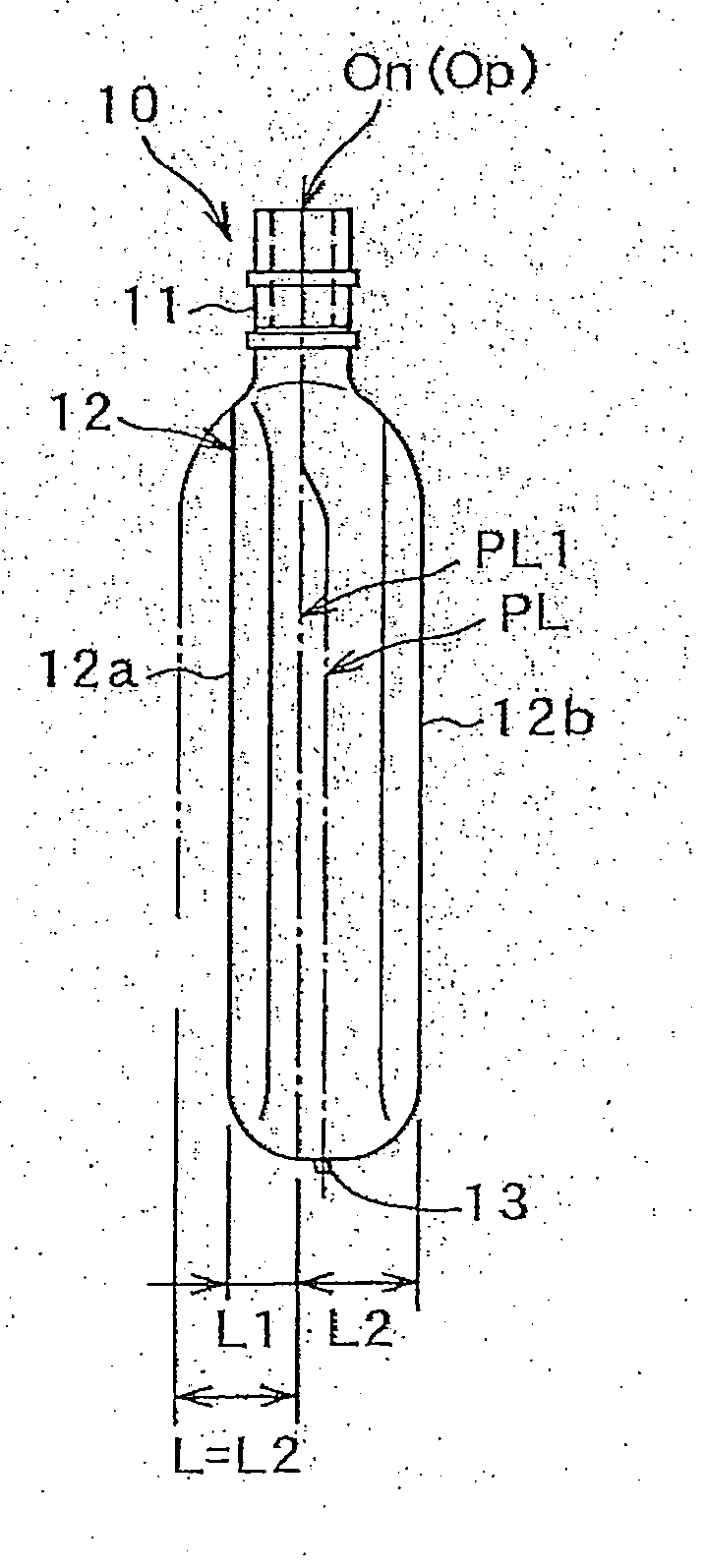
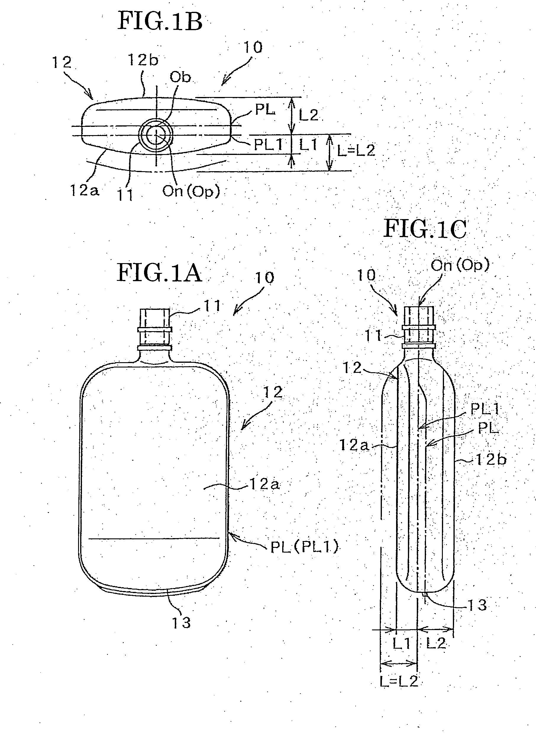
[0038]FIG. 1 shows a front view, a plan view and a side view of an embodiment of a fuel bottle for a fuel cell of the present invention.

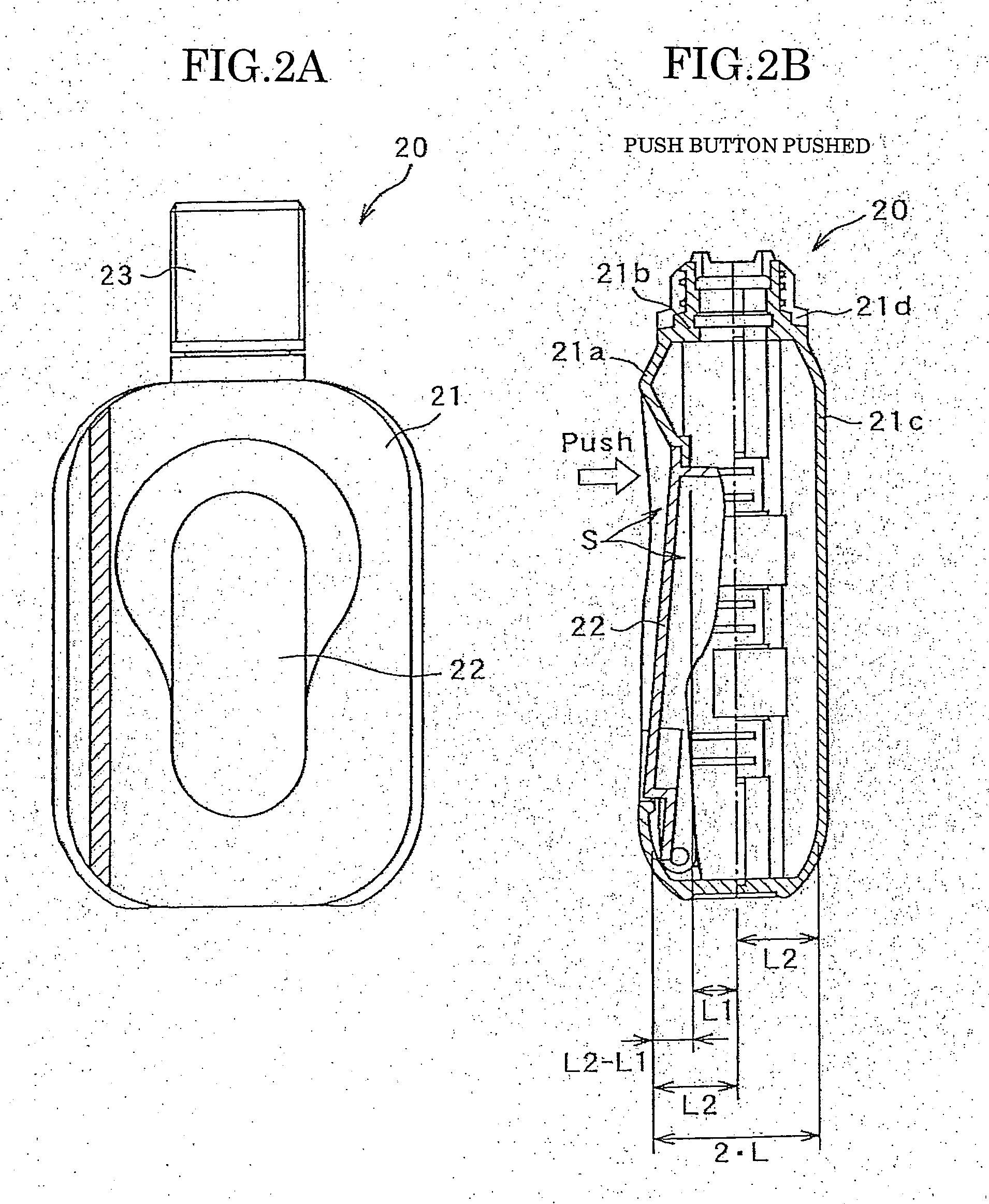
[0039]FIG. 2 shows a front view and a sectional view of an embodiment of a fuel cartridge of the invention using the fuel bottle for a fuel cell. FIG. 3 shows a sectional view of a blow mold used for molding the fuel bottle for a fuel cell of the invention and FIG. 4 shows a front view, a plan view and a side view of another embodiment of a fuel bottle for a fuel cell of the invention.

[0040]A fuel bottle 10 for a fuel cell is a fuel bottle for containing methanol for a passive type fuel cell according to which fuel is directly supplied to a fuel tank of a fuel cell main body of a direct methanol fuel cell (DMFC) using methanol as its fuel.

[0041]This fuel bottle 10 is formed, as shown in FIG. 1, is made of plastic having contractibil...


PUM

PropertyMeasurementUnit
lengthaaaaaaaaaa
shapeaaaaaaaaaa
strengthaaaaaaaaaa

Abstract

A fuel bottle 10 for a fuel cell having a bottle main body 12 for containing fuel for a fuel cell and comprising a nozzle portion 11 at the tip portion of the bottle main body 12 on which a coupler for connecting with a main body of a fuel cell can be attached and a trunk portion having a generally elliptic shape in cross section and having been formed by blow molding. In this bottle 10, length L1 in one direction of minor axis from the center On of the nozzle portion of the elliptic shape in cross section differs from length L2 in the other direction of the minor axis from the center On of the nozzle portion. By this structure, a moving space of a push button when the fuel bottle 10 is housed in a hard case can be secured while necessary capacity of the fuel bottle 10 is secured. Pinch portions 13 and 14 are formed in lowly stretched portions of the bottle main body 12 in a manner to protrude outwardly whereby contact areas of the pinch portions 13 and 14 are increased and contact strength thereby is improved.

Description

TECHNICAL FIELD[0001]This invention relates to a fuel bottle for a fuel cell and a fuel cartridge using the same which can achieve a shape, capacity and strength adapted for containing methanol fuel for a methanol fuel cell and for housing the bottle in a hard case and being capable of flowing out methanol fuel by pushing a push button and adapted also for forming the bottle by blow molding.BACKGROUND ART[0002]Various liquid type fuel cells capable of generating electric current directly from liquid fuel have recently been developed. A direct methanol fuel cell (DMFC) using methanol as fuel has attracted attention as a power source of mobile type electronic devices, for it does not need a reformer and therefore can be made in a compact design.[0003]In a direct methanol fuel cell (DMFC) called a passive system, in particular, methanol which is a liquid fuel is supplied directly by coupling a fuel cartridge containing methanol to a fuel tank provided on the main body of a fuel cell wh...

Claims


Application Information

Patent Timeline
Patent Type & Authority Applications(United States)
IPC IPC(8): B65D90/02
CPCB29C49/04B29L2031/7156B29L2031/7172H01M8/04208H01M8/1011Y02E60/523Y02E60/50B65D1/32B65D77/04H01M8/04
Inventor TANAKA, KENJIROUTANAKA, MASAYOSHINARUTAKI, KOUICHIANDOH, KENJITAKAHASHI, KENICHI
Owner TOYO SEIKAN KAISHA LTD
Why Eureka
Try Eureka