Method and system for auto positioning compression mechanism in a mammography system

a compression mechanism and mammography technology, applied in mammography, medical science, diagnostics, etc., can solve the problems of reducing the accuracy of the biopsy operation, affecting the patient's recovery, so as to prevent any accidental collisions, prevent physical damage during the operation, and enhance patient safety

Inactive Publication Date: 2010-04-29
GENERAL ELECTRIC CO
View PDF9 Cites 3 Cited by
  • Summary
  • Abstract
  • Description
  • Claims
  • Application Information

AI Technical Summary

Benefits of technology

[0044]The automation ensures precise calculations of the positions where the puncture needle must enter the breast during biopsy operation and the depth it should go when biopsy is initiated.
[0045]By using the invention the mammography system is made safer to operate, intelligent enough to auto position and prevent any physical damages while in operation. Also this results in workflow improvements resulting in relief to the operator and patient.
[0046]Further enhanced patient safety is achieved by preventing any accidental possibilities of collisions between the compression mechanism and the breast biopsy device. This is especially important to prevent accidents during imaging operations and biopsy operations.
[0047]The ope

Problems solved by technology

However there are certain problems associated with the image gantry rotation.
This might result in a collision between the breast biopsy device and the compression mechanism.
It may also be startling or scary for the patient to hear the sound of a collision while the biopsy is being performed, which may cause the patent to move and decrease the accuracy of the biopsy operation.
However, the sound of adjusting the compression mechanism while the patient is undergoing biopsy operation may itself be startling or scary for the patient.
Further the need of operating the compression mechanism manually during an acquisition or biopsy operation can result in breast or patient movements, requiring re-acquisition.
Further the operation of raising the compression mechanism manually is time consuming and may cause discomfort to the patient.
Manual adjustment of the compression mechanism is also subject to error.

Method used


Image

  • Method and system for auto positioning compression mechanism in a mammography system
  • Method and system for auto positioning compression mechanism in a mammography system
  • Method and system for auto positioning compression mechanism in a mammography system

Examples


Embodiment Construction

[0021]In the following detailed description, reference is made to the accompanying drawings that form a part hereof, and in which is shown by way of illustration specific embodiments that may be practiced. These embodiments are described in sufficient detail to enable those skilled in the art to practice the embodiments, and it is to be understood that other embodiments may be utilized and that logical, mechanical, electrical and other changes may be made without departing from the scope of the embodiments. The following detailed description is, therefore, not to be taken as limiting the scope of the invention.

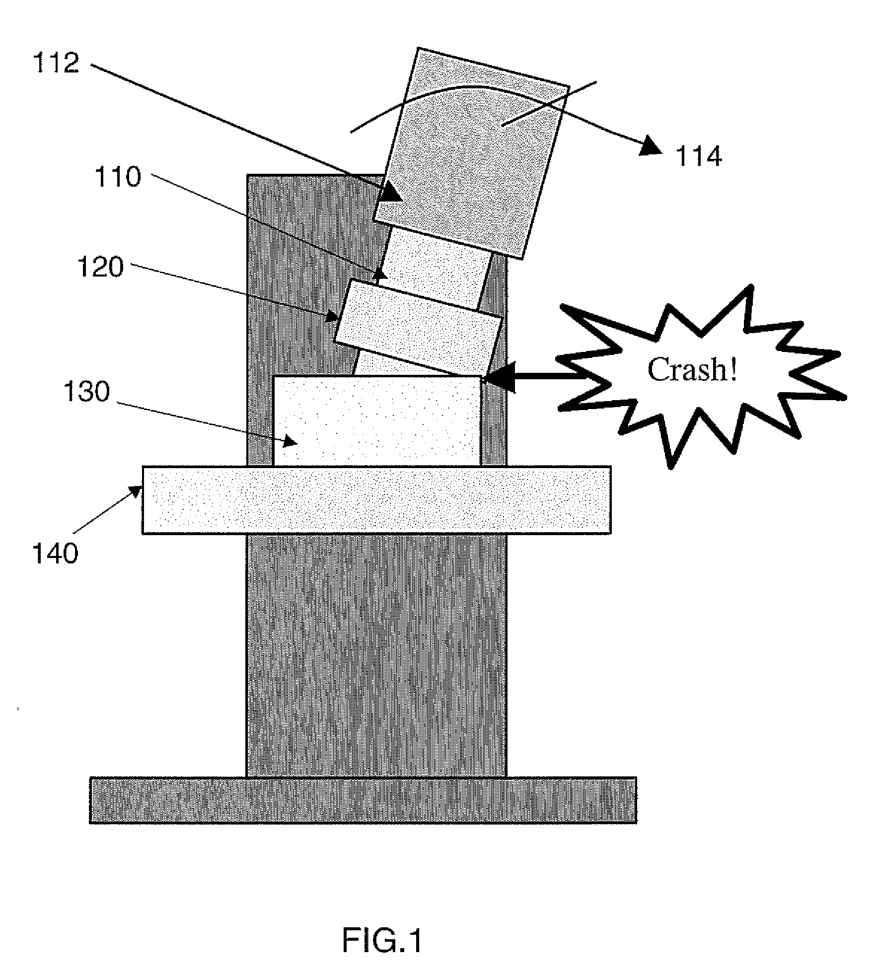
[0022]Various embodiments of the present invention are directed to methods and systems for automatically adjusting the position of a breast compression mechanism, such as a breast compressor, a breast holding paddle, or a paddle holder, in a mammography system upon detection of a breast biopsy operation. The breast biopsy device is detected upon connecting the device to the ma...


PUM


Abstract

A method and system for auto positioning a compression mechanism in a mammography imaging system is disclosed herewith. The method comprises: automatically elevating the compression mechanism upon detection of a breast biopsy device. The breast biopsy device can be detected upon connecting the same to the mammography system or can be detected upon noticing the same on the vicinity of the mammography system. The compression mechanism includes: breast compressor, breast holding paddles and paddle holders.

Description

FIELD OF THE INVENTION[0001]This invention relates generally to mammography methods and systems, and more particularly to, a method and system for automatically adjusting the position of a compression mechanism in a mammography system upon detecting the presence of a breast biopsy device.BACKGROUND OF THE INVENTION[0002]Mammography has earned a great deal of significance, as it's a method for detecting signs of breast cancer. Many times, biopsies are done using breast biopsy devices in association with mammography systems.[0003]Generally, a breast biopsy is done using a breast biopsy device connected to a mammography system. The mammography system takes different images of a breast and, with reference to the same, the biopsy operation is performed. For imaging, the breast needs to be compressed and in a mammography system generally the breasts are compressed using a compression mechanism. However while carrying out the breast biopsy operation, a breast biopsy device is connected and...

Claims


Application Information

Patent Timeline
IPC IPC(8): A61B6/04
CPCA61B6/0414A61B6/502A61B10/0233A61B6/4494A61B2019/205A61B2019/4857A61B2019/5238A61B19/20A61B90/10A61B90/17A61B2090/376A61B2090/0811
Inventor BINDRA, GAGANHERSEMEULE, GUY
Owner GENERAL ELECTRIC CO
Why Eureka
Try Eureka