
Device for minimizing neck and head injury

a head and neck technology, applied in the field of head support devices, can solve the problems of life-threatening, head injury, neck or brain injury, and insufficient head protection in most vehicle seats, and achieve the effects of reducing the potential for such injuries, reducing the potential for head injuries, and reducing the movement of the head

Inactive Publication Date: 2010-04-29
BWI LLC
View PDF36 Cites 34 Cited by
  • Summary
  • Abstract
  • Description
  • Claims
  • Application Information

AI Technical Summary

Benefits of technology

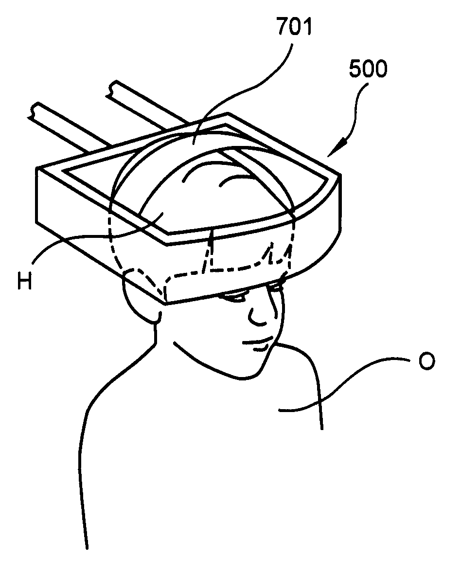
[0019]In the broadest embodiment the invention is an adjustable head restrain that is connected to a seat of a vehicle, wherein the head restraint encircles the entire head to prevent rapid or jarring head movement during a sudden or rapid change of speed or orientation of the seat. The most common situation would involve a car crash. The encircling head restrain is attached to the seat such that it is easily adjustable to the proper location on the head. The device is defined herein as a support halo because it encircles the top of the head, much like a halo depicted in a Medieval or Renaissance church painting (see for example the “Lamentation of Christ” in the Scrovegni Chapel in Padua, Italy by Giotto di Bondone (circa 1305)), but like the modern version worn by countless children in church plays, this halo is held in position by a post or a series of posts. It is a support halo because it is designed to support the head and thereby protect the neck in the event of the kind of jarring movement of the body in the seat that would normally cause the head to move violently.

Problems solved by technology

Injury to the head, neck or brain has the potential to be sever, and in some situations even life threatening.
The head is not adequately secured in most vehicle seats.
It is slightly larger than the head and is not designed to actually fit snuggly on the head.
Touching the head would be uncomfortable and increase the likelihood that a person, particularly a child, would try to squirm out of the halo.

Method used


Image

  • Device for minimizing neck and head injury
  • Device for minimizing neck and head injury
  • Device for minimizing neck and head injury

Examples


Embodiment Construction

[0070]Detailed embodiments of the present invention are disclosed herein. It is to be understood that the disclosed embodiments are merely exemplary of the invention and that the invention may be embodied in various and alternative forms. Therefore, specified structural and functional details disclosed herein are not to be interpreted as limitations, but merely as a basis for the claims and as a representative basis for teaching one skilled in the art to variously employ the present invention.

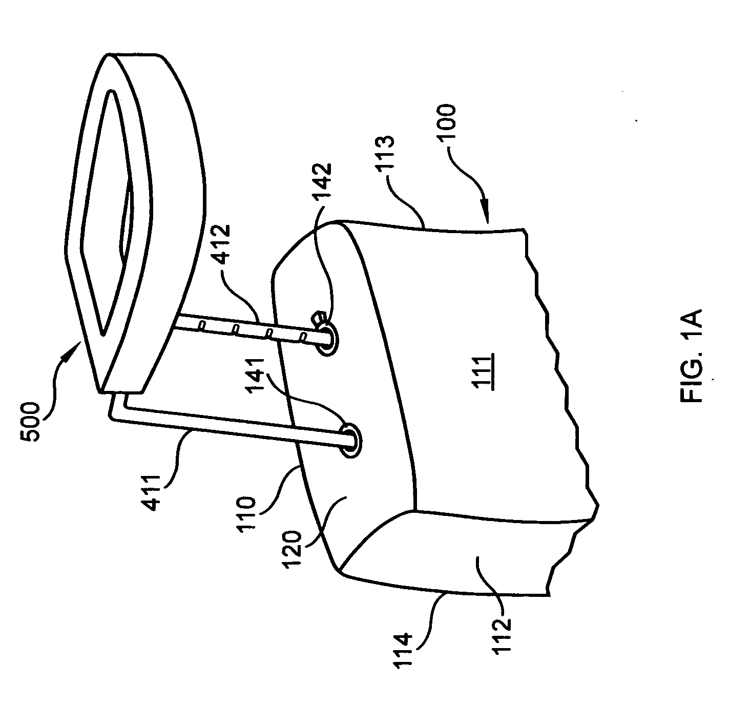
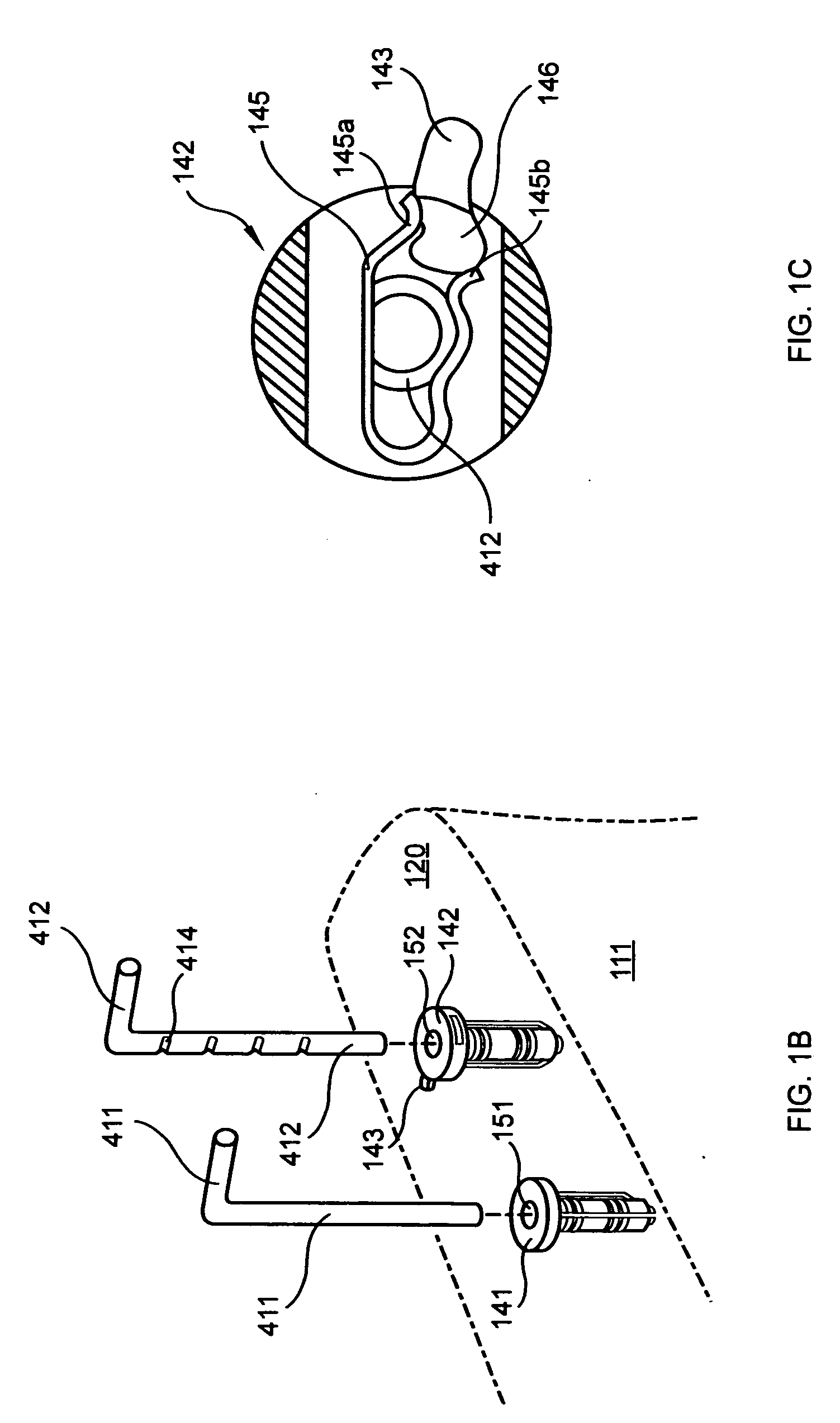
[0071]The invention comprises an encircling head support and restraint attached to the seat of a moving vehicle. FIGS. 1A, 2A, 2B, 3A &3B depict the most common embodiments of the disclosed invention. FIG. 1A depicts the support halo 500 attached to a standard automobile car seat 100. FIGS. 2A & 2B depict the support halo 500 attached to a typical child protective car seat 200. FIGS. 3A & 3B depicts the support halo 500 attached to a typical child's booster seat 300. There are minor variations ...


PUM


Abstract

An encircling head restraint rigidly though movably attached to a seat within a vehicle, such that in the event of a crash or other sudden movement, the head of the occupant of the seat is protected, and excess movement of the head and neck is prevented. The encircling head restraint sits around the head, but does not touch the head so that the occupant can move the head within the encircling head restraint. The encircling head restraint prevents excess movement of the head in all directions. In a preferred embodiment the encircling head restraint is movably mounted to a child's car seat such that it can be adjusted up or down to fit properly on the head of the child. The encircling head restraint is adjustable to accommodate different sized heads. There is a hinge mechanism that allows the encircling head restraint to be easily moved out of the way to allow easy access to the seat by the occupant.

Description

CROSS REFERENCE TO RELATED APPLICATIONS[0001]This application is a continuation-in-part, and claims priority to U.S. Non-Provisional patent application Ser. No. 12 / 288,858 filed on Oct. 24, 2008.STATEMENT REGARDING FEDERALLY SPONSORED RESEARCH OR DEVELOPMENT[0002]Not Applicable.THE NAMES OF THE PARTIES TO A JOINT RESEARCH AGREEMENT[0003]Not Applicable.INCORPORATION-BY-REFERENCE OF MATERIAL SUBMITTED ON A COMPACT DISC[0004]Not Applicable.FIELD OF THE INVENTION[0005]The present invention relates to a device for protecting the neck and head during an accident such as an automobile accident. More particularly the present invention related to a head support device that is attached to a seat in a moving vehicle. More particularly still, the present invention relates to an encircling head restrain that is movably and adjustably attached to the seat of a vehicle, or a seat secured in a vehicle such as a conventional child's protective car seat or booster seat, wherein the encircling head re...

Claims


Application Information

Patent Timeline
IPC IPC(8): B60R21/02B60N2/48B60N2/26B60N2/28
CPCB60N2/2821B60N2/2851B60N2/4882B60N2/2872B60N2/4817B60N2/2866B60N2/818B60N2/885
Inventor BARNES, STEPHEN B.WOOD, DAVID M.BEWLEY, WILBURZORNES, ROCKYGEORGE, IVAN M.
Owner BWI LLC
Learn More