
Twist and lock connection for pleated filter element with flange-to-flange locking means

a technology of pleated media and filter elements, which is applied in the direction of separation process, filtration separation, transportation and packaging, etc., can solve the problems of inability to easily replace fabric filter bags with certain barriers to the replacement of fabric filter bags by and the inability to install relatively long and rigid pleated media filter cartridges without considerable manipulation

Active Publication Date: 2010-04-29
PARKER INTANGIBLES LLC
View PDF10 Cites 44 Cited by
  • Summary
  • Abstract
  • Description
  • Claims
  • Application Information

AI Technical Summary

Benefits of technology

[0010]The above summary presents a simplified summary in order to provide a basic understanding of some aspects of the systems and / or methods discussed herein. This summary is not an extensive overview of the systems and / or methods discussed herein. It is not intended to identify key / critical elements or to delineate the scope of such systems and / or methods. Its sole purpose is to present some concepts in a simplified form as a prelude to the more detailed description that is presented later.

Problems solved by technology

Although many baghouses are made according to this basic structure, there may be numerous operational and structural differences among baghouses.
However, certain barriers to easy replacement of fabric filter bags by pleated media filter cartridges exist.
A relatively long and rigid pleated media filter cartridge cannot be installed without considerable manipulation if it can be installed at all due to the limited access space in the clean air plenum.
This presents a problem for filter manufacturers because there are effective limits as to the width of the filter media that can be pleated with current production machinery.
The current production machinery used to pleat filter media typically cannot accommodate continuous filter media more than about two meters in width.
Such a long filter cartridge would also be relatively difficult to handle, transport and install.
Such threaded connectors are difficult to connect when there are imperfections in the threads themselves, and efforts to minimize formation of such imperfections during manufacturing have proven to be expensive.
And despite best efforts to minimize such imperfections during manufacturing, an unacceptable number of incompatibly-threaded connectors that will be difficult to connect may still result.

Method used


Image

  • Twist and lock connection for pleated filter element with flange-to-flange locking means
  • Twist and lock connection for pleated filter element with flange-to-flange locking means
  • Twist and lock connection for pleated filter element with flange-to-flange locking means

Examples


Embodiment Construction

[0020]Certain terminology is used herein for convenience only and is not to be taken as a limitation on the present invention. Relative language used herein is best understood with reference to the drawings, in which like numerals are used to identify like or similar items. Further, in the drawings, certain features may be shown in somewhat schematic form.

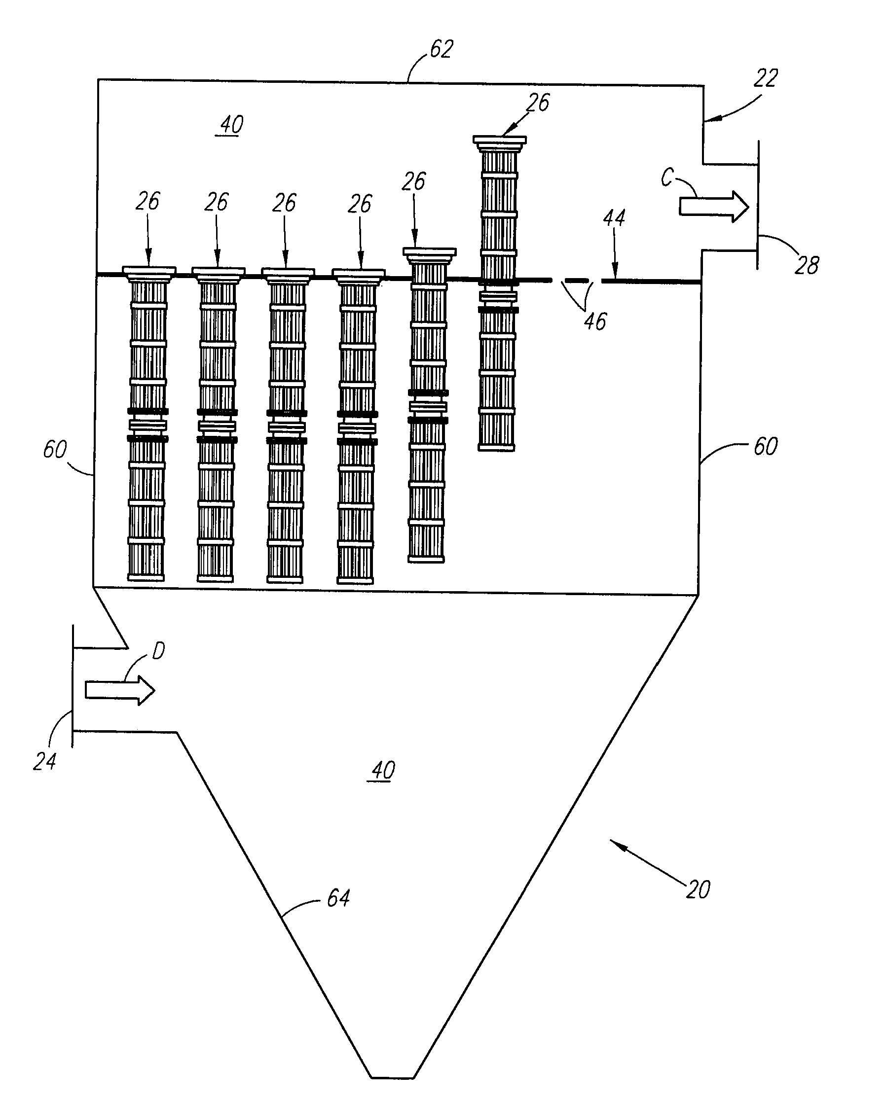
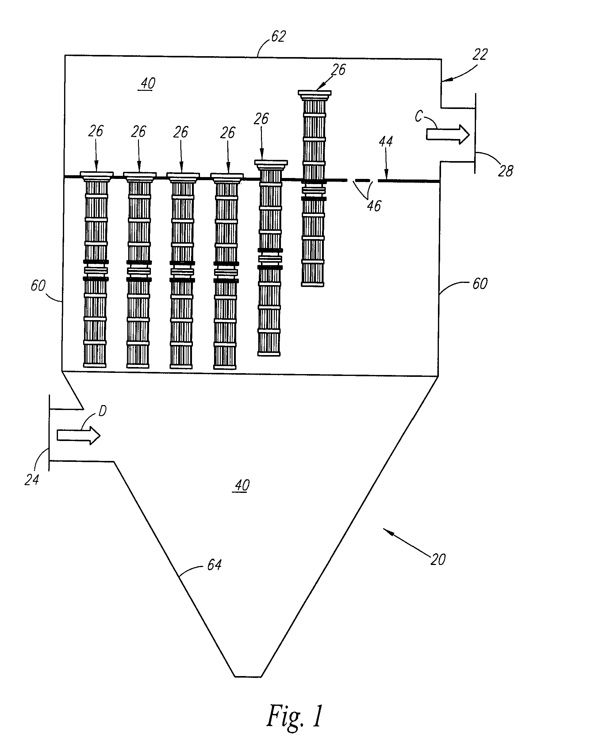
[0021]A baghouse 20 is illustrated in FIG. 1. The baghouse 20 is defined by an enclosed housing 22. The housing 22 is made from a suitable material, such as sheet metal. Particulate laden gas D flows into the baghouse 20 from an inlet 24. The particulate laden gas D is filtered by a plurality of relatively long cartridges or filter assemblies 26 (best seen in FIG. 2) constructed according to one aspect of the invention located within the baghouse 20. Cleaned gas C exits through an outlet 28 of the baghouse 20.

[0022]The baghouse 20 is divided into a “dirty air” plenum 40 and a “clean air” plenum 42 by a tube sheet 44 made from a sui...


PUM

PropertyMeasurementUnit
Dimensionaaaaaaaaaa

Abstract

A baghouse and filter assembly are provided for at least partially removing particulate matter from a gas stream. The filter assembly includes first and second filter portions to be coupled together by a coupler for establishing fluid communication between the first and second filter portions when connected. The coupler includes a first coupling portion including a side wall defining an interior passage through which the gas stream can pass in an axial direction between the first and second filter portions, and one or more flanges projecting from said side wall, the one or more flanges supporting a plurality of male studs. The coupler further includes a second coupling portion including a plurality of female keyhole-shaped receivers spaced apart for receiving at least a portion of the male studs and coupling the first coupling portion to the second coupling portion.

Description

FIELD OF THE INVENTION[0001]The present invention relates generally to a filter assembly for use in a baghouse. In particular, the present invention relates to connecting structure for a multi piece filter assembly having pleated filter elements.BACKGROUND OF THE INVENTION[0002]There is increasing environmental regulatory control throughout the world. Much of the regulatory control is focused on reducing air-borne pollutants and emissions from certain industrial sources, such as power plants and materials production facilities. A known technique to control the pollutants and emissions from the industrial sources is to separate undesirable particulate matter that is carried in a gas stream by fabric filtration. Such fabric filtration is accomplished in a dust collection apparatus known in the industry as a “baghouse.”[0003]The baghouse typically includes a housing divided into two plenums by a tube sheet. One plenum is a “dirty air” plenum which communicates with an inlet and receive...

Claims


Application Information

Patent Timeline
IPC IPC(8): B01D46/02
CPCB01D46/0021B01D46/2414B01D2265/022B01D2265/021B01D46/521B01D2201/4038B01D46/60
Inventor CLEMENTS, JACK T.MADDOCKS, GERRY E.
Owner PARKER INTANGIBLES LLC
Learn More