
Pseudo Wire Establishing Method and Device

a technology of pseudo wires and establishing methods, applied in electrical devices, digital transmission, data switching networks, etc., can solve the problems of increasing the cost of nodes and preventing other functions from being mounted, and achieve the effect of excluding useless resources of pseudo wires and lightening the receiving capacity

Inactive Publication Date: 2010-04-22
FUJITSU LTD
View PDF13 Cites 11 Cited by
  • Summary
  • Abstract
  • Description
  • Claims
  • Application Information

AI Technical Summary

Benefits of technology

The present invention provides a method and device for establishing a pseudo wire in a network that can reduce unnecessary resources and improve processing capacity. The method involves selecting an MPLS tunnel with a remaining resource for a pseudo wire and distributing information of the selected MPLS tunnel to the opposing device. The device includes a mechanism for selecting an MPLS tunnel based on priorities and notifying the opposing device of the selected MPLS tunnel. The technical effect of this invention is to optimize the use of network resources and improve processing capacity by avoiding unnecessary resources and optimizing the distribution of pseudo wires.

Problems solved by technology

Thus, for a receiving capacity of pseudo wires at an end node or device (Egress node) distributing pseudo wire labels, such a waste that each interface is required to have a processing capacity of overall node is caused, resulting in an cost increase of the node and a disadvantage of precluding other functions to be mounted due to a resource (bandwidth) wasted.

Method used


Image

  • Pseudo Wire Establishing Method and Device
  • Pseudo Wire Establishing Method and Device
  • Pseudo Wire Establishing Method and Device

Examples


embodiment 1

b>-12

[1] Distribution of MPLS Tunnel Label

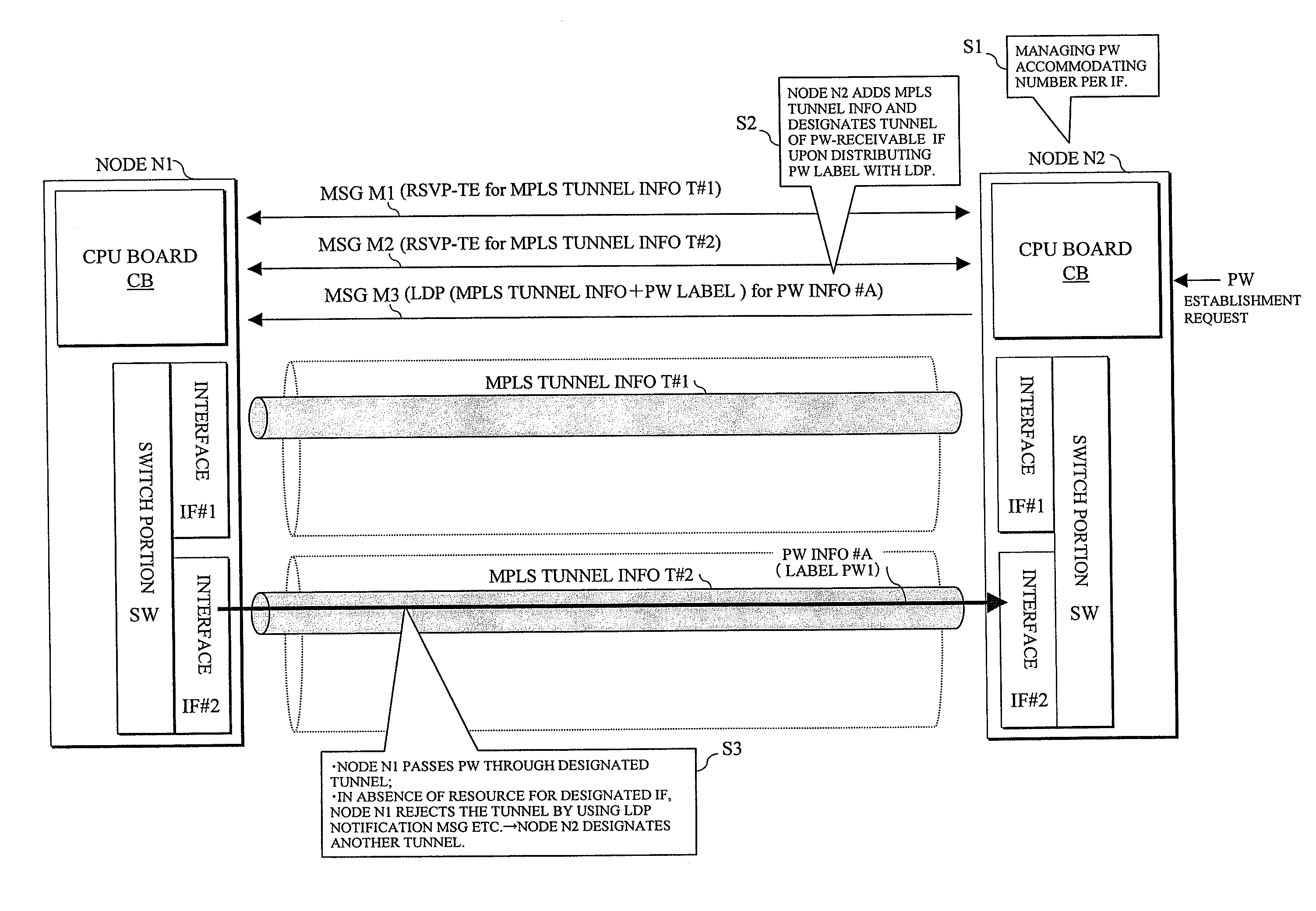
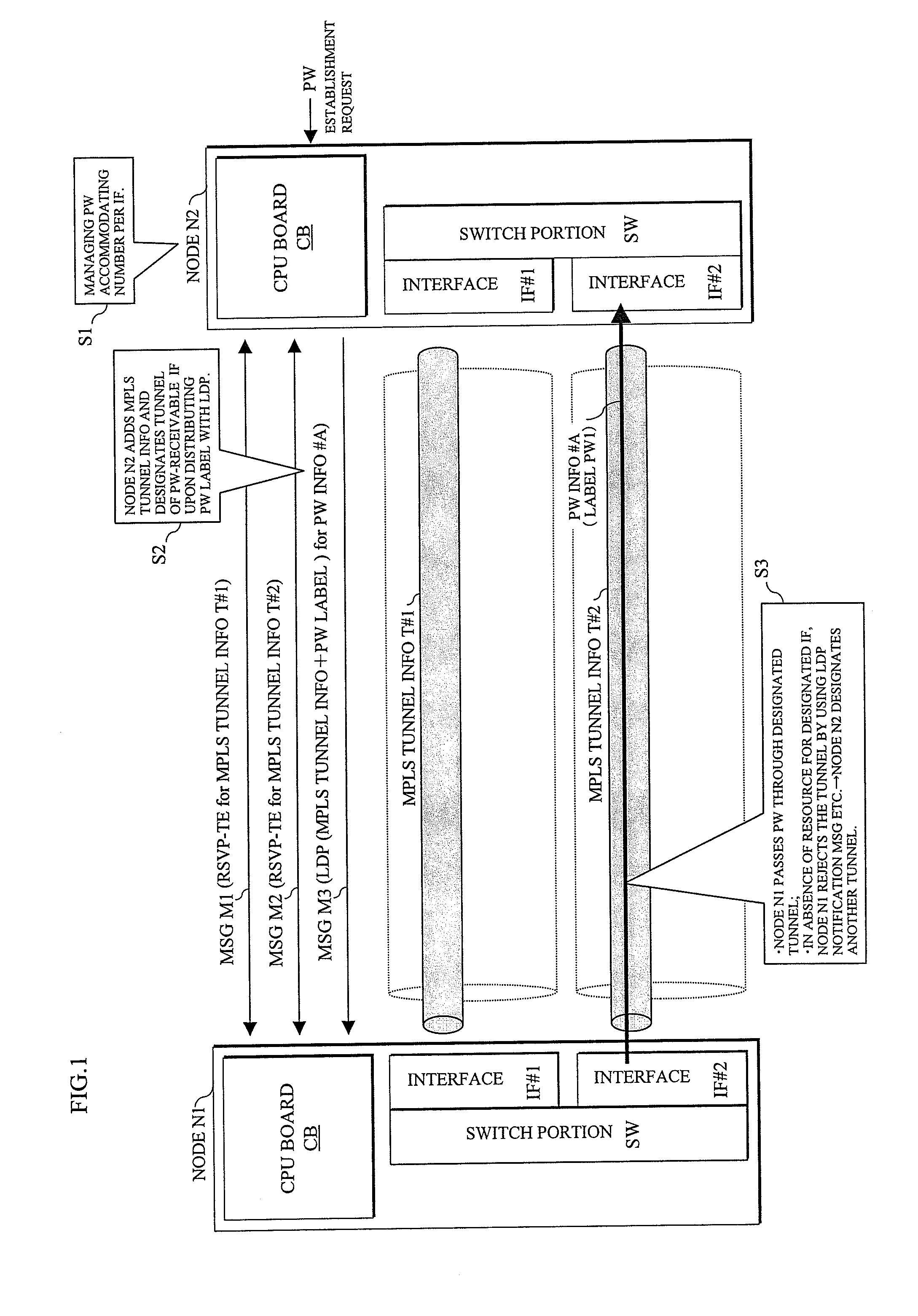
[0083]Label distribution processes (1)-(5) of MPLS tunnels shown in FIG. 4 are similar to those of the related art shown in FIG. 19, so that the same descriptions are hereinafter omitted.

[0084]Thus, in FIG. 5, like the related art in FIG. 21, MPLS tunnel labels are distributed in both directions between the nodes N1-N2 with the messages M1-1-M2-2, MPLS tunnels of the MPLS tunnel information T#1-1 and T#1-2 are established between the interfaces IF#1 of the nodes N1 and N2 and MPLS tunnels of the MPLS tunnel information T#2-1 and T#2-2 are established between the interfaces IF#2 similarly.

[2] Distribution of PW Label

[0085]FIG. 6 shows an MPLS / PW associated processing on the side of the node N2 after the MPLS tunnels have been thus established, where as shown in FIG. 4 it is assumed that the node N2 (PW receiving side) receives a PW establishment request at this point. It is to be noted that there is a case that the node N1 also receives a PW ...

embodiment 2

/ b>-17

[0105]FIG. 13 showing an overall operation according to this Embodiment 2 partially includes the operation of Embodiment 1 shown in FIG. 4 and an operation of FIG. 14 also partially includes the operations shown in FIG. 5 as noted above. Furthermore, an MPLS / PW associated processing on the side of the node N1 shown in FIG. 15 and an MPLS / PW associated processing on the side of the node N2 shown in FIG. 17 in Embodiment 2 respectively correspond to the MPLS / PW associated processings shown in FIGS. 6 and 10 in Embodiment 1.

[1] Distribution of MPLS Tunnel Labels

[0106]At first, in FIG. 13, processes (1)-(5) are the same as those in the distribution of the MPLS tunnel labels shown in FIGS. 4 and 19, so that the same descriptions are hereinafter omitted.

[2] Distribution of PW Labels

[0107](6) It is assumed in this Embodiment 2 that a PW establishment request is provided to the node N1 after having completed the label distribution of the MPLS tunnels as noted above (step S31, S36). In...


PUM


Abstract

For precluding useless resources of a pseudo wire in a device distributing pseudo wires to lighten the receiving capacity, MPLS (Multi Protocol Label Switching) tunnels are established with an opposing device. From among the established MPLS tunnels, an MPLS tunnel having a remaining resource for a pseudo wire at interfaces having the MPLS tunnels in response to a pseudo wire establishment request is selected and the information of the selected MPLS tunnel associated with a label of the pseudo wire having the remaining resource is distributed to the opposing device. Alternatively after having established the MPLS tunnels with the opposing device, when a distribution request of the pseudo wire information associated with desired MPLS tunnels is received from the opposing device having received the pseudo sire establishment request, a label of the pseudo wire is similarly determined and distributed to the opposing device together with the information of the MPLS tunnel passing the pseudo wire.

Description

CROSS-REFERENCE TO RELATED APPLICATION[0001]This application is related to and claims priority to Japanese Patent Application No. 2008-268917, filed on Oct. 17, 2008, in the Japanese Patent Office, and incorporated by reference.BACKGROUND [0002]1. Field[0003]The present invention relates to a pseudo wire establishing method and device and in particular to a method and device for passing a pseudo wire between opposing nodes or devices based on MPLS (Multi Protocol Label Switching) tunnels established.[0004]2. Description of the Related Art[0005]While MPLS has been remarkable as a recent packet transmission technology, a specification review and standardization of PWE3 (Pseudo Wire Emulation Edge-to-Edge; hereinafter referred to as pseudo wire or abbreviated as PW) offering the existing services (FR, ATM, TDM, Ethernet) over End-to-End (Point-to-Point) with a tunneling technology of MPLS have been promoted.[0006]Through such an MPLS tunnel and pseudo wire in an MPLS network MNW betwee...

Claims


Application Information

Patent Timeline
Patent Type & Authority Applications(United States)
IPC IPC(8): H04L12/28H04L45/50H04L47/76
CPCH04L45/68H04L12/4633
Inventor HIROTA, MASAKI
Owner FUJITSU LTD
Learn More