
Electrophoretic sheet, electrophoresis apparatus, method for manufacturing an electrophoresis apparatus and electronic device

Inactive Publication Date: 2010-04-22
E INK CORPORATION
View PDF9 Cites 7 Cited by
  • Summary
  • Abstract
  • Description
  • Claims
  • Application Information

AI Technical Summary

Benefits of technology

[0013]It is an object of the present invention to provide an electrophoretic sheet capable of increasing whiteness in display of electrophoretic particles and constructing an electrophoresis apparatus with a superior contrast ratio, a highly reliable electrophoresis apparatus, a method for manufacturing an electrophoresis apparatus capable of easily and reliably manufacturing the electrophoresis apparatus, and a highly reliable electronic device.

Problems solved by technology

For this reason, the combined use of a PET-ITO substrate and titanium oxide as white particles in producing an electrophoresis apparatus reduces whiteness in display, which entails a problem of reducing a white and black contrast and a sharpness of an image.

Method used


Image

  • Electrophoretic sheet, electrophoresis apparatus, method for manufacturing an electrophoresis apparatus and electronic device
  • Electrophoretic sheet, electrophoresis apparatus, method for manufacturing an electrophoresis apparatus and electronic device
  • Electrophoretic sheet, electrophoresis apparatus, method for manufacturing an electrophoresis apparatus and electronic device

Examples


first embodiment

[0068]1 Electrophoresis Apparatus

[0069]First, description will be made on an electrophoresis apparatus (the present electrophoresis apparatus) to which an electrophoretic sheet of the present invention is applied.

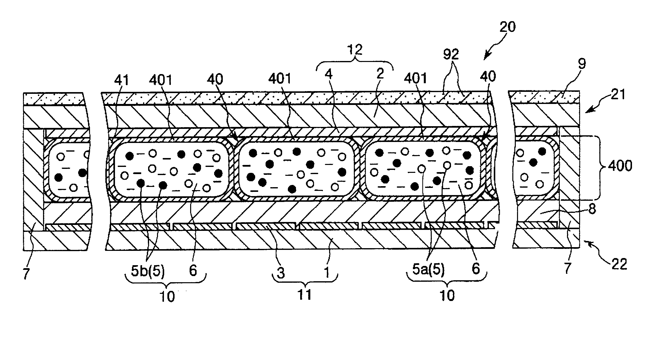
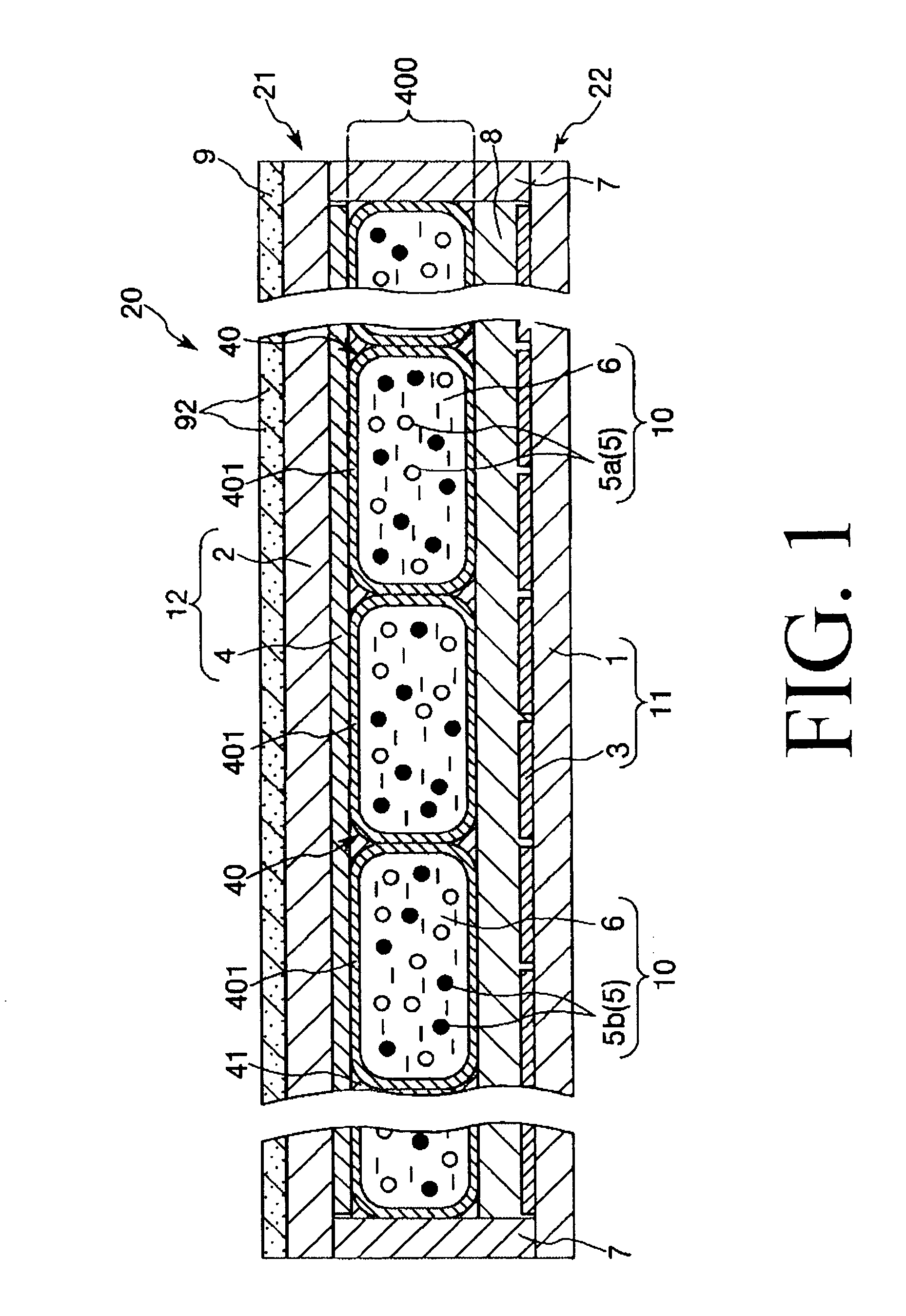
[0070]FIG. 1 is a pattern diagram showing a vertical section of a first embodiment of the electrophoresis apparatus according to the present invention. Hereinafter, the upper side in FIG. 1 will be referred to as “upper” and the lower side will be referred to as “lower” for the purpose of convenience in description.

[0071]The electrophoresis apparatus 20 shown in FIG. 1 includes an electrophoretic sheet (front plane) 21, a circuit board (back plane) 22, an adhesive agent layer 8 for bonding the electrophoretic sheet 21 and the circuit board 22 together, and a sealing part 7 for air-tightly sealing a gap between the electrophoretic sheet 21 and the circuit board 22.

[0072]The electrophoretic sheet 21 includes a substrate 12, which has a plate-like base portion 2 and a second e...

second embodiment

[0206]Next, description will be made on a second embodiment of an electrophoresis apparatus to which an electrophoretic sheet of the present invention is applied.

[0207]FIG. 5 is a pattern diagram showing a vertical section of a second embodiment of the electrophoresis apparatus according to the present invention. Hereinafter, the upper side in FIG. 5 will be referred to as “upper” and the lower side will be referred to as “lower” for the purpose of convenience in description.

[0208]An electrophoresis apparatus of the second embodiment will now be described with emphasis placed on the points differing from the electrophoresis apparatus of the first embodiment set forth above. Description will be omitted regarding the same matters.

[0209]The electrophoresis apparatus 20 shown in FIG. 5 is the same as the electrophoresis apparatus 20 of the first embodiment, except that the transmission part 9 is not formed on the upper surface of the base portion 2 and the base portion 2 serves as a tra...

third embodiment

[0214]Next, description will be made on a third embodiment of an electrophoresis apparatus to which an electrophoretic sheet of the present invention is applied.

[0215]FIG. 6 is a pattern diagram showing a vertical section of a third embodiment of the electrophoresis apparatus according to the present invention. Hereinafter, the upper side in FIG. 6 will be referred to as “upper” and the lower side will be referred to as “lower” for the purpose of convenience in description.

[0216]An electrophoresis apparatus of the third embodiment will now be described with emphasis placed on the points differing from the electrophoresis apparatus of the first embodiment set forth above. Description will be omitted regarding the same matters.

[0217]The electrophoresis apparatus 20 shown in FIG. 6 is the same as the electrophoresis apparatus 20 of the first embodiment, except that a cover layer 90 constituting a transmission part 9 is provided so as to cover the outer circumferential surface of the ca...


PUM

PropertyMeasurementUnit
Thicknessaaaaaaaaaa
Wavelengthaaaaaaaaaa
Transmittivityaaaaaaaaaa

Abstract

An electrophoretic sheet includes a substrate having one surface and the other surface, a microcapsule-containing layer comprised of a plurality of microcapsules, the microcapsule-containing layer provided on the other surface of the substrate, each of the plurality of microcapsules having a capsule body and an electrophoretic dispersion liquid contained in the capsule body, the electrophoretic dispersion liquid containing a plurality of electrophoretic particles of at least one color, and the capsule body having an inner circumferential surface and an outer circumferential surface, and at least one colored part provided on the external side of the inner circumferential surface of the capsule body of each of the plurality of microcapsules, and wherein each colored part has a color complementary to the color of the plurality of electrophoretic particles. By using the electrophoretic sheet mentioned above, it is possible to provide the increased whiteness in display of the electrophoretic particles. An electrophoresis apparatus provided with such an electophoretic sheet is also provided. By using the electrophoresis apparatus, it is possible to provide a superior contrast ratio. It is also possible to obtain high reliability. A Method for manufacturing such an electrophoresis apparatus is also provided. An electronic device provided with such an electrophoresis apparatus is also provided.

Description

CROSS-REFERENCE TO RELATED APPLICATION[0001]This application claims a priority to Japanese Patent Application No. 2007-046266 filed on Feb. 26, 2007 which is hereby expressly incorporated by reference herein in its entirety.BACKGROUND[0002]1. Technical Field[0003]The present invention relates to an electrophoretic sheet, an electrophoresis apparatus, a method for manufacturing an electrophoresis apparatus and an electronic device.[0004]2. Related Art[0005]It is generally known that, if electric fields are allowed to act on a dispersion system in which fine particles are dispersed in liquid, the fine particles move (or migrate) through the liquid under the influence of a coulomb force. This phenomenon is referred to as electrophoresis. In recent years, an electrophoresis apparatus that displays desired information (images) using the electrophoresis draws attention as a new display apparatus.[0006]The electrophoresis apparatus is characterized by exhibiting display memory characterist...

Claims


Application Information

Patent Timeline
IPC IPC(8): G02F1/167B32B37/02G02F1/16757
CPCG02F1/167G02F1/16757
Inventor KOMATSU, HARUNOBUYAMAMOTO, HITOSHIKUSHINO, MITSUOKUWAMOTO, TOMOYUKI
Owner E INK CORPORATION
Learn More