Furnace filter alert

a technology of filter alert and furnace, which is applied in the direction of alarm, instruments, flue gas purification components, etc., can solve the problems of allergy polluting and poor indoor air quality

Inactive Publication Date: 2010-04-22
SWORD TECH CORP
View PDF6 Cites 5 Cited by
  • Summary
  • Abstract
  • Description
  • Claims
  • Application Information

AI Technical Summary

Problems solved by technology

Too much dust and dirt on a filter will cause the fan motor and furnace equi...

Method used


Image

  • Furnace filter alert
  • Furnace filter alert
  • Furnace filter alert

Examples


Embodiment Construction

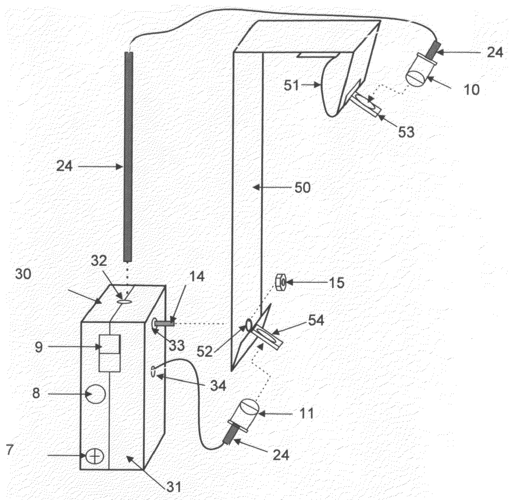
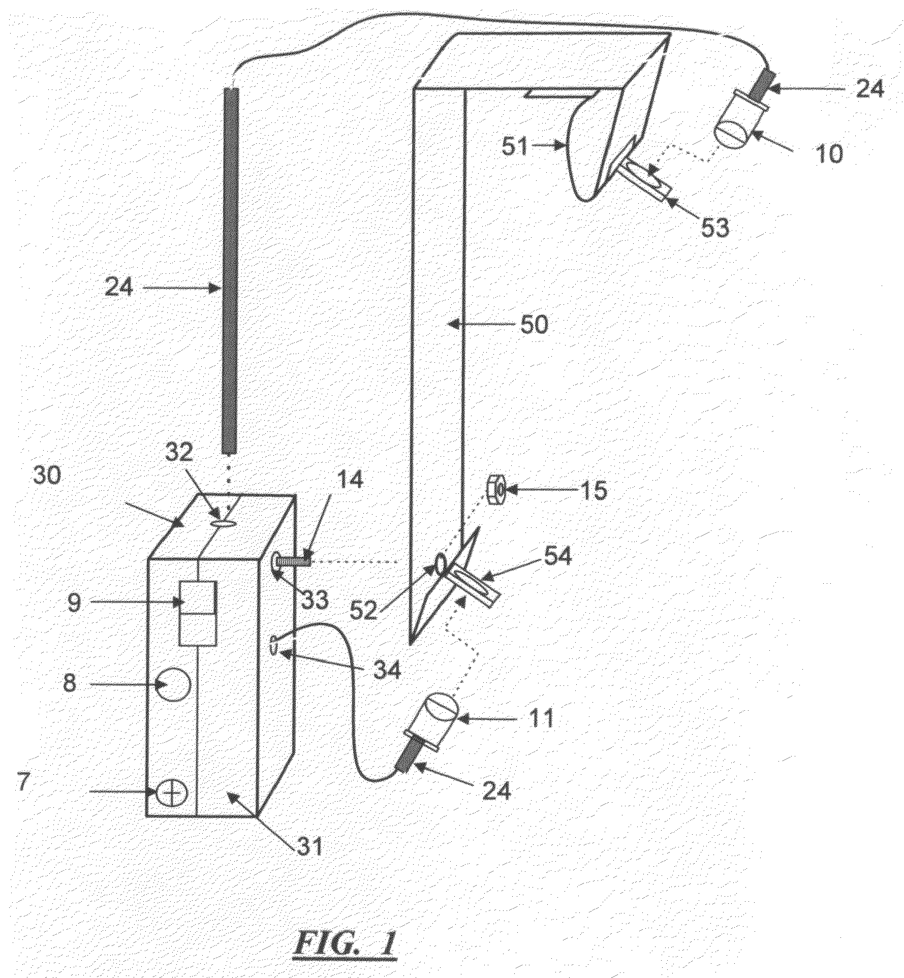
[0041]FIG. 1 is an exploded 3D view of the Filter Alert device subassembly. It shows how the emitter (10) and detector (11) attach to the hanging arm (50) by Upper LED holder (53) and Lower LED holder (54). The Upper LED holder (53) and Lower LED holder (54) are glue to the hanging arm (50). The back case (31) connects to hanging arm (50) by way of screw (14) and the nut (15) securing them together.

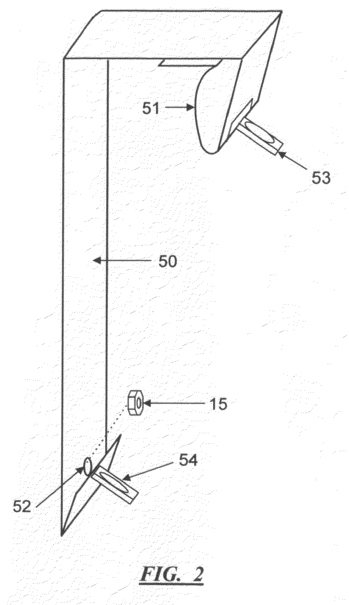
[0042]FIG. 2 shows the said hanging arm used to attach the Filter Alert device shown in FIG. 1 on the filter's backside. The hanging arm s holding spring (51) located on the said hanging arm which spring back into its position to firmly secure itself to the filter achieve the securing of the Filter Alert device to a filter. FIG. 2 also shows the upper LED mount (53) and the lower LED mount (54) which attaches to the hanging arm (50). The said hanging arm can be made of aluminum metal but its preferred that fireproof plastic used so that the paper filter will not become deformed when said ...


PUM


Abstract

A dust particle detector comprised of one or more light beam emitters (10) and detectors (11), mounted on a hanging arm (50) which is attached to rear case (31). Enclosed in front case (30) and said rear case, a buzzer (4), battery (1), control potentiometer (5), switch (9) and electronic chips (2 and 3). After hanging the Filter Alert on the furnace filter, the light beam path soon becomes block with dust and dirt, which triggers the buzzer (4).

Description

FIELD OF THE INVENTION[0001]The present invention relates to an alarm device adapted to be removable / attached to a furnace filter to alarm when dirt and / or dust accumulate on the filter surface.BACKGROUND OF INVENTION[0002]Changing the furnace filter on a regular interval helps prolong the furnace life and keep it working more efficiently. Furnace filters are usually out of sight and out of mind. Too much dust and dirt on a filter will cause the fan motor and furnace equipment to stop working thus making the indoor air quality poor and allergy polluted.[0003]The Filter Alert will aid in the prevention of the damage to the fan motor and furnace equipment and will help remind the user to change the filthy furnace filter.BRIEF DESCRIPTION OF THE DRAWINGS[0004]FIG. 1—is a detailed exploded perspective view of the Filter Alert assembly.[0005]FIG. 2—is a detail elevation view of the Clamp assembly 3D view.[0006]FIG. 3—is an exploded view of Filter Alert front case with PC board.[0007]FIG....

Claims


Application Information

Patent Timeline
IPC IPC(8): G08B21/00
CPCF22B37/38F22B37/008
Inventor LARSON-KOLOMYJEC, SUZANNESEALES, MAUNUEL D.
Owner SWORD TECH CORP
Why Eureka
Try Eureka