
Device for positioning at least one orthodontic element

a technology for placing devices and orthodontic elements, applied in the field of orthodontics, can solve the problems of limited accuracy of standard direct bonding methods, limited possibility of uniquely placing jigs in patients' mouths, and difficulty in regulating the amount of pressure exerted on each brack

Inactive Publication Date: 2010-04-15
DENTSPLY IMPLANTS NV
View PDF17 Cites 69 Cited by
  • Summary
  • Abstract
  • Description
  • Claims
  • Application Information

AI Technical Summary

Benefits of technology

[0020]It is an object of embodiments of the present invention to provide good apparatus or methods for positioning at least one orthodontic element on the dentition of a patient or on a physical model of a dentition.
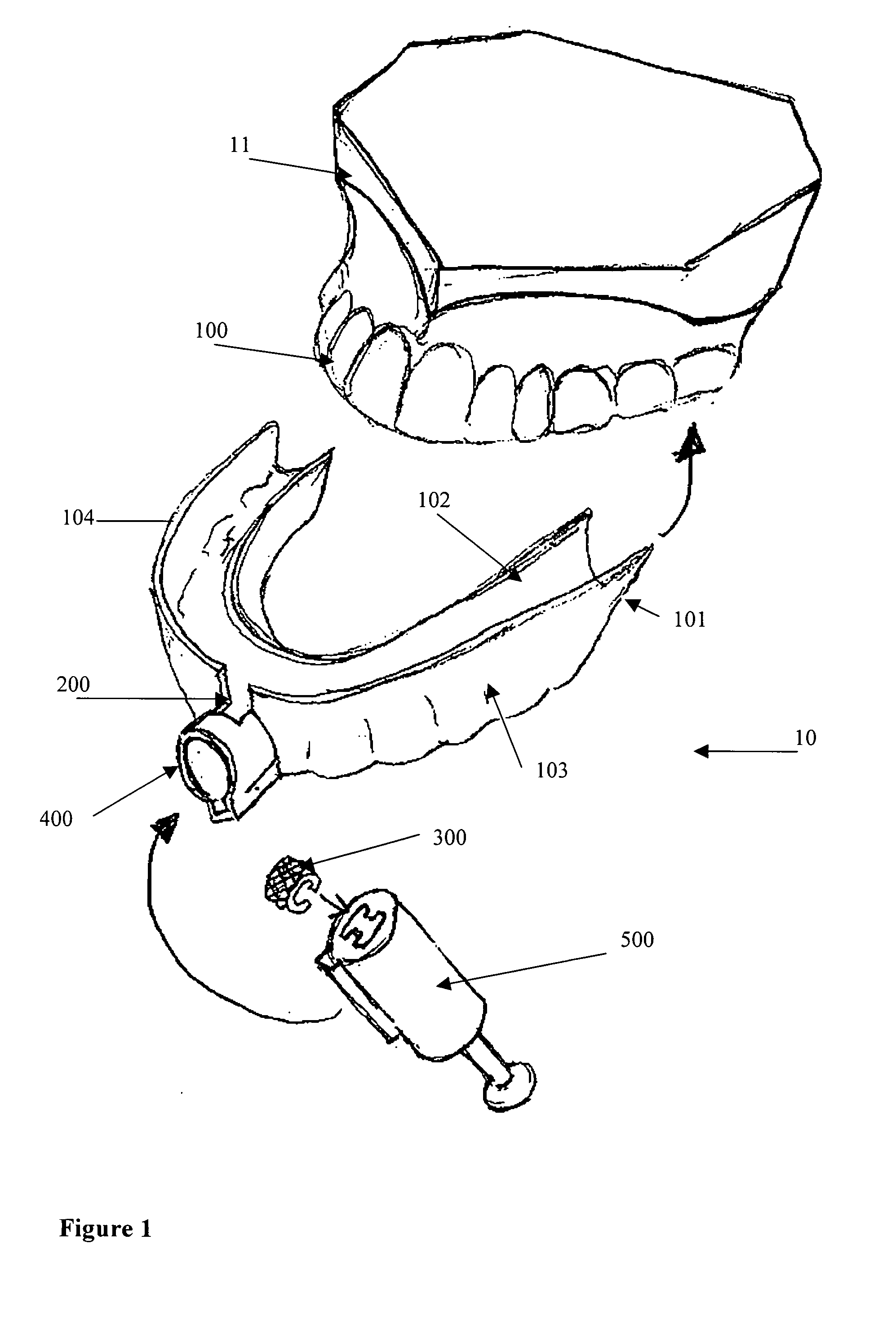
[0022]It is an advantage of embodiments of the present invention that at least one of the limitations of the techniques mentioned above is overcome. The present invention, in embodiments thereof, provides a device for transferring a computer planning of placement of orthodontic elements (such as brackets) to a physical part via guided direct bonding. The physical part can be the dentition of a patient or a physical model of a dentition. Guidance denotes limiting the movement of the orthodontic element, e.g. bracket, during placement with one or more degrees of freedom. The present invention, in embodiments thereof, further provides a device for positioning at least one orthodontic element on the dentition of a patient or on a physical model of a dentition, which device has a reduced risk in misaligning the orthodontic element on the dentition of the model of the dentition. The present invention, in embodiments thereof, further provides a method for producing a device for positioning at least one orthodontic element on the dentition of a patient or on a physical model of a dentition, which device is based on computer planning of orthodontic elements to a dentition of a patient.
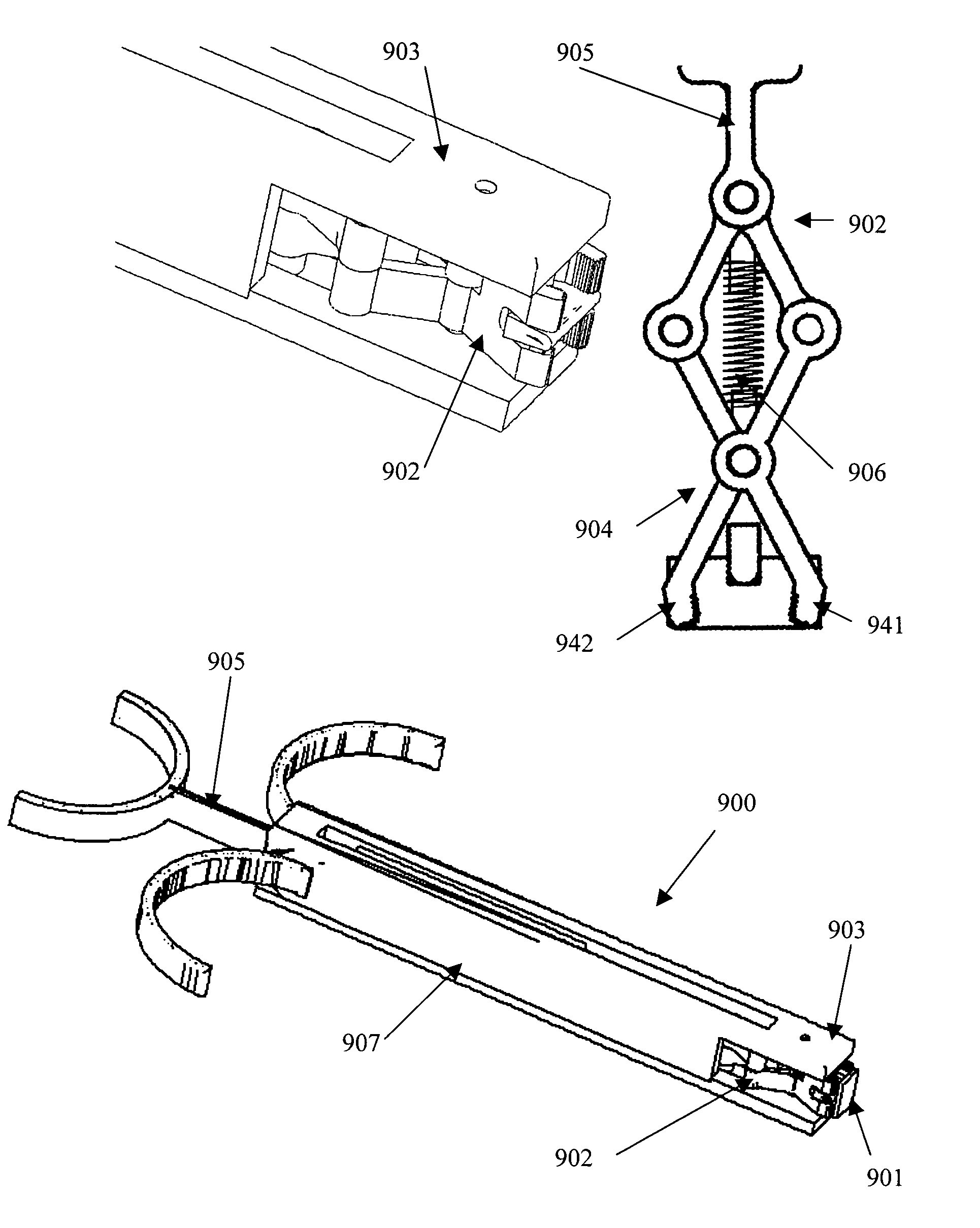
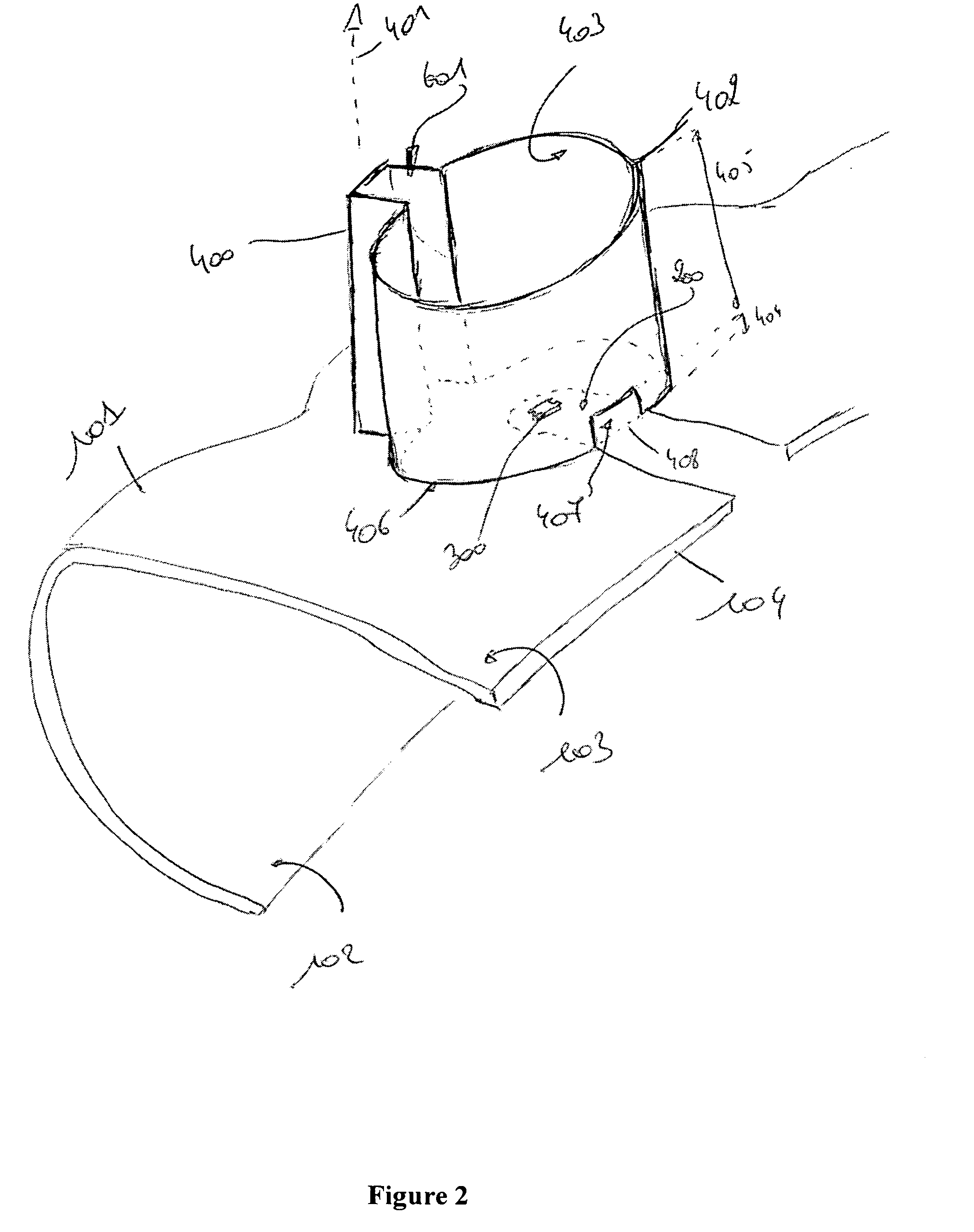
[0032]The device according to embodiments of the present invention allows the orthodontic element holder to move and thereby bring the orthodontic element to the exact place on the dentition or the dentition model. As the guide extends from the positioning template outwardly, i.e. in a direction opposite to the dentition, the orthodontic element holder may be guided along a path, which extends from the positioning template's inner surface. This corresponds to the direction along which the orthodontist usually will bring the orthodontic element to the position on the dentition or model of the dentition. The guide being extended with respect to the positioning template provides optimal guidance. With embodiments according to the present invention, a more accurate guiding may be obtained. This is in particular very helpful in case the orthodontic element is to be positioned on molars, which are more difficult to reach with orthodontic instruments, since the cheek may obstruct approximation of the side surfaces of the molars. Malpositioning of the orthodontic elements, such as brackets, is minimised, if not avoided. The device is also advantageous when used for placing orthodontic elements at the lingual side of the tooth or teeth. Orthodontic elements, such as brackets, are glued onto the non-visible lingual faces of the teeth. This is difficult because of a lack of visibility. The method and device according to embodiments of the invention allow orthodontic elements to be placed without the necessity to visually see the location where the orthodontic element is brought in contact with the lingual side of the tooth.
[0074]The teachings of the present invention permit the design of improved methods for placing orthodontic elements to a dentition of a patient, which method allows more correct and reliable placing of the orthodontic element. By creating a positioning template optionally fit uniquely to at least a part of the dentition of the patient or at least a part of a model of the dentition, and, once the positioning template is placed on this part of the dentition or model, guiding the orthodontic element or elements via guides extending outwards from the positioning template (i.e. on the outer surface of the positioning template, in a direction away from the inner surface), the orthodontic element can be guided to a unique position and orientation for contacting, and optionally gluing, binding or coupling it, to the tooth of the dentition.

Problems solved by technology

However the standard direct bonding method has a limited accuracy since it involves taking the bracket with tweezers and pressing it to the tooth surface at the location which is the best according to the orthodontist's judgment.
A problem with this method is that it is difficult to regulate the amount of pressure which is exerted on each bracket.
The limited width of the jigs, however, limits the possibility of uniquely placing the jig in the patient's mouth.
This technique requires a substantial training of the orthodontist, since he has to learn how to work with the system.
Moreover there is a substantial risk of malpositioning the brackets since the operator can easily position the brackets differently than planned.
Creating an indirect bonding tray via this method requires a substantial amount of manual work: a plaster model has to be created, each bracket has to be bonded to the model individually and creating the trays also requires human interaction.
Drawback of this procedure is that the positioning of the sheet is not unique, since it is only the judgment of the user that decides whether it is positioned correctly.
Moreover, there is no control whether the bracket is positioned precisely as indicated by the sheet.
This approach requires a sophisticated and expensive computer guided robot for positioning the brackets on the model.
Moreover, it still requires the production of a physical model of the patient's dentition and the manual fabrication of a transfer device.
This is obviously an expensive procedure, since it requires the creation of both a model of placement and the actual jig.
This implies that this system can only be used with specifically designed brackets having the appropriate hole.
A disadvantage of this system is the very limited contact which is possible between the template and the bracket base because of the small dimensions of the latter.
Individual jigs created via this approach still have the drawback that their position is not unique on all teeth.
Jigs covering a few teeth don't allow a controlled pressure per bracket anymore.
Moreover, the rigidity of the jigs makes it impossible to bond a large portion of the dentition at once, since the bonded brackets would obstruct the jig or even prevent its removal.

Method used


Image

  • Device for positioning at least one orthodontic element
  • Device for positioning at least one orthodontic element
  • Device for positioning at least one orthodontic element

Examples


Embodiment Construction

[0086]The present invention will be described with respect to particular embodiments and with reference to certain drawings but the invention is not limited thereto but only by the claims. The drawings described are only schematic and are non-limiting. In the drawings, the size of some of the elements may be exaggerated and not drawn on scale for illustrative purposes. The dimensions and the relative dimensions do not correspond to actual reductions to practice of the invention.

[0087]Furthermore, the terms first, second, third and the like in the description and in the claims, are used for distinguishing between similar elements and not necessarily for describing a sequence, either temporally, spatially, in ranking or in any other manner. It is to be understood that the terms so used are interchangeable under appropriate circumstances and that the embodiments of the invention described herein are capable of operation in other sequences than described or illustrated herein.

[0088]More...


PUM


Abstract

A device (10) is provided for positioning at least one orthodontic element (300) on a dentition (100) by means of an orthodontic element holder (500) for holding at least one orthodontic element (300). The device (10) comprises a positioning template (101) for fitting on at least a part of the dentition (100). The positioning template (101) has at least one open area (200) for allowing an orthodontic element (300) to contact the dentition (100). The positioning template (101) has an inner surface (102) for contacting the at least a part of the dentition (100). The positioning template (101) is further provided with at least one guide (400) coupled to and extending from the positioning template (101) in a direction away from the dentition (100) when the inner surface (102) is in contact with the dentition (100). The at least one guide (400) is suitable for cooperating with an orthodontic element holder (500) for guiding the orthodontic element (300) held by the orthodontic element holder (500) to the at least one open area (200).

Description

TECHNICAL FIELD OF THE INVENTION[0001]This invention relates to the field of orthodontics and more specifically to bonding techniques for placing an orthodontic element, such as a bracket, on a dentition comprising teeth or on a physical model of a dentition comprising teeth, which techniques are based on a computer planning. The present invention further relates to a method to provide a device for positioning at least one orthodontic element on the dentition of a patient or on a physical model of a dentition, and to a device for positioning at least one orthodontic element on the dentition of a patient or on a physical model of a dentition.BACKGROUND OF THE INVENTION[0002]The aim of orthodontic treatment is to correctly position and orient a patient's teeth. This can be done by using removable or fixed appliances which are in contact with the teeth and exert a force on them. The term fixed appliances usually refers to the well-known brackets or bands which are glued or cemented ont...

Claims


Application Information

Patent Timeline
Patent Type & Authority Applications(United States)
IPC IPC(8): A61C7/02G06F17/50
CPCA61C7/146A61C7/002
Inventor ESPOSTI, ALESSIOVAN ROIE, BERTVAN LIERDE, CARL
Owner DENTSPLY IMPLANTS NV
Learn More