
Max-min fair network bandwidth allocator

a network bandwidth and allocator technology, applied in the direction of digital transmission, data switching networks, electrical equipment, etc., can solve the problems of inexact and computationally inefficient approaches to designing a method to achieve mmf allocation of available bandwidth, and inefficient approaches

Active Publication Date: 2010-04-15
TELLABS OPERATIONS
View PDF1 Cites 12 Cited by
  • Summary
  • Abstract
  • Description
  • Claims
  • Application Information

AI Technical Summary

Benefits of technology

[0008]In one example embodiment of the invention, a procedure for allocating an amount of available bandwidth among a plurality of users of a computer network is provided. Each user has a maximum allocation of bandwidth. Tier information of a plurality of tiers is accessed. In the tier information, users are grouped according to maximum allocation, and the tier information includes a breakpoint value of each tier. The available bandwidth is allocated by (1) allocating the maximum allocations to the users in tiers with breakpoint values less than or equal to the amount of available bandwidth, and (2) allocating a remaining amount of available bandwidth in a fair manner among remaining users, which are the users in tiers with breakpoint values greater than the amount of available bandwidth. In one example, the breakpoint value of at least one tier is an amount of bandwidth that must be allocated in a Max-Min fair manner among the plurality of users such that each user in the tier receives its maximum allocation of bandwidth.
[0009]According to an example aspect of the invention, the breakpoint value of the lowest tier equals a product of the lowest maximum allocation and a total number of users in the plurality of users, and the breakpoint value of at least one higher tier equals the sum of (1) the breakpoint value of a lower tier and (2) the product of (a) a number of users in tiers corresponding to maximum allocations greater than that associated with the lower tier and (b) a difference between a higher maximum allocation associated with the at least one higher tier and a lower maximum allocation associated with the lower tier. According to an example embodiment of the invention, the lower tier is a next, lower tier than the lower tier.
[0010]In another example embodiment of the invention, each user has a weight, a normalized maximum allocation of bandwidth, and a maximum allocation of bandwidth that is the product of the weight and the normalized maximum allocation. Tier information of a plurality of tiers is accessed. In the tier information, users are grouped according to normalized maximum allocation, and the tier information includes a breakpoint value of each tier. The available bandwidth is allocated by (1) allocating maximum allocations to the users in tiers with breakpoint values less than or equal to the amount of available bandwidth, and (2) allocating a remaining amount of available bandwidth in a weighted fair manner among remaining users, which are the users in tiers with breakpoint values greater than the amount of available bandwidth. The breakpoint value of a tier is an amount of bandwidth that must be allocated in a weighted Max-Min fair manner among the plurality of users such that each user in the tier receives its maximum allocation of bandwidth.

Problems solved by technology

However, Max-Min fairness is a principle whose definition is not “constructive.” In other words, while the principle of MMF provides an objective end result of an allocation, MMF definition does not provide a method to achieve this final allocation.
Some existing approaches to designing a method to achieve MMF allocation of available bandwidth are both computationally inefficient and inexact.
This approach is inefficient because it is likely to involve a large number of iterations, each of which involves memory accesses, comparisons with a user's maximum allocation, and arithmetic operations to increment the allocation.
This approach is also inexact, since it is limited in precision by the size of the unit of bandwidth allocation.

Method used


Image

  • Max-min fair network bandwidth allocator
  • Max-min fair network bandwidth allocator
  • Max-min fair network bandwidth allocator

Examples


Embodiment Construction

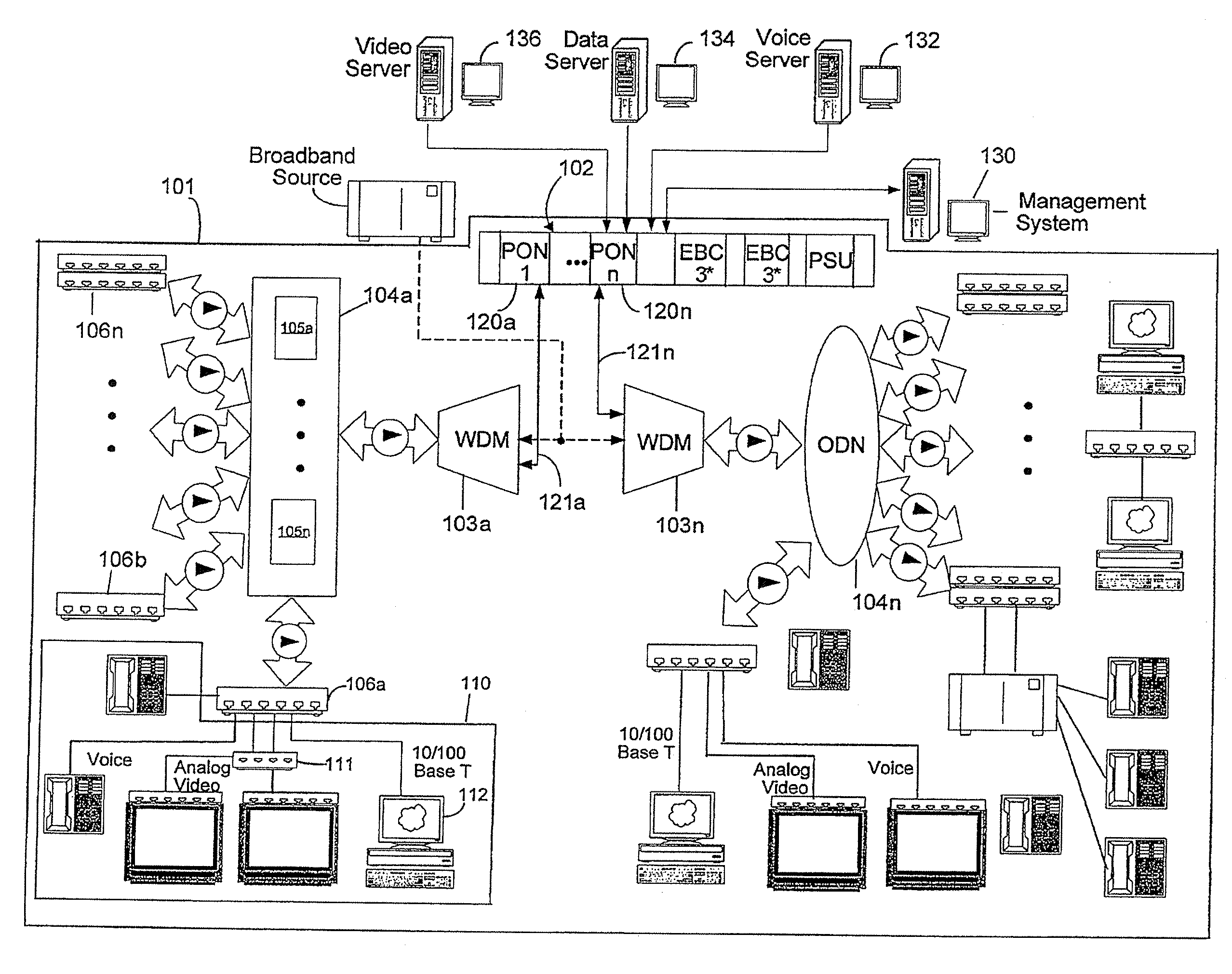
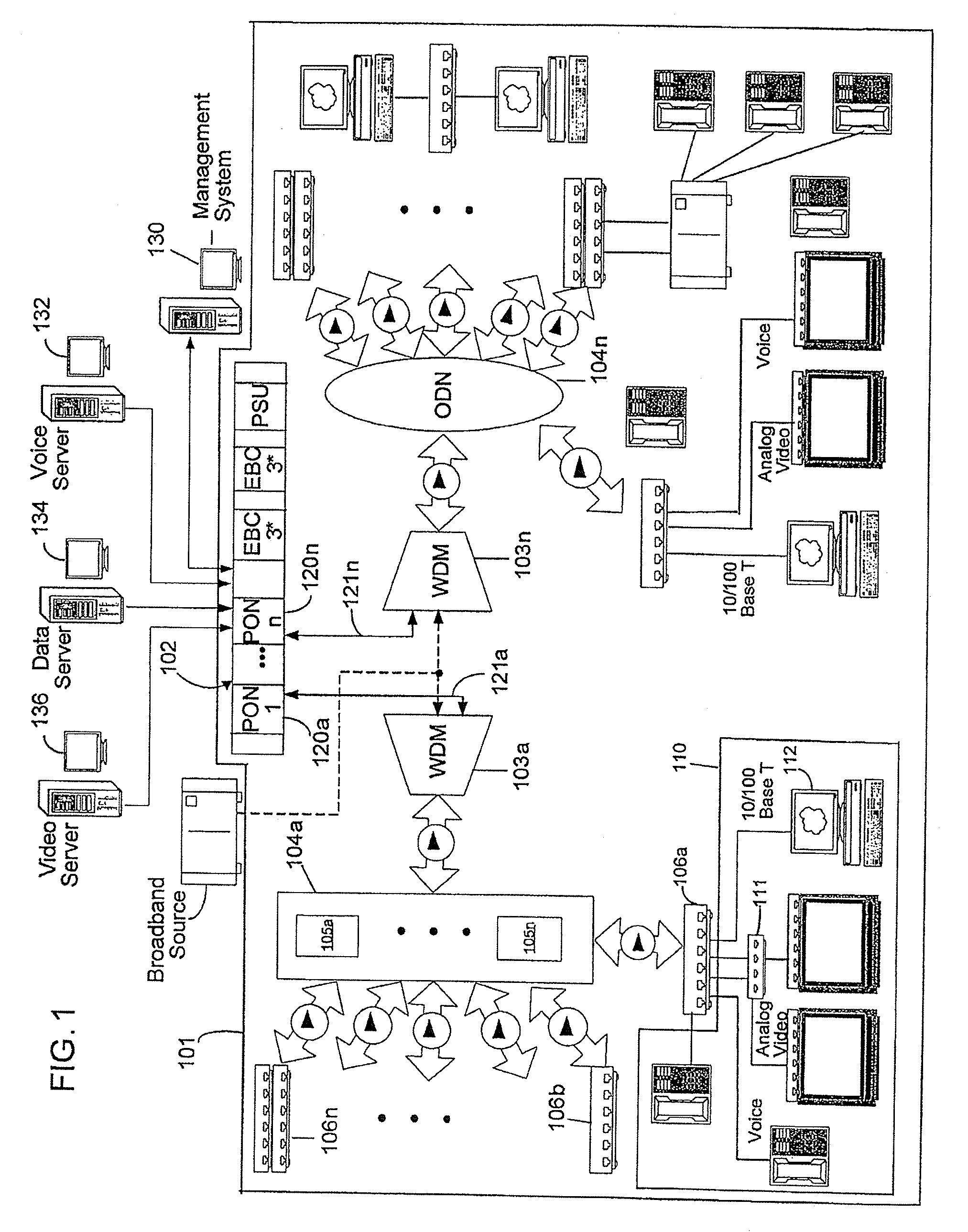
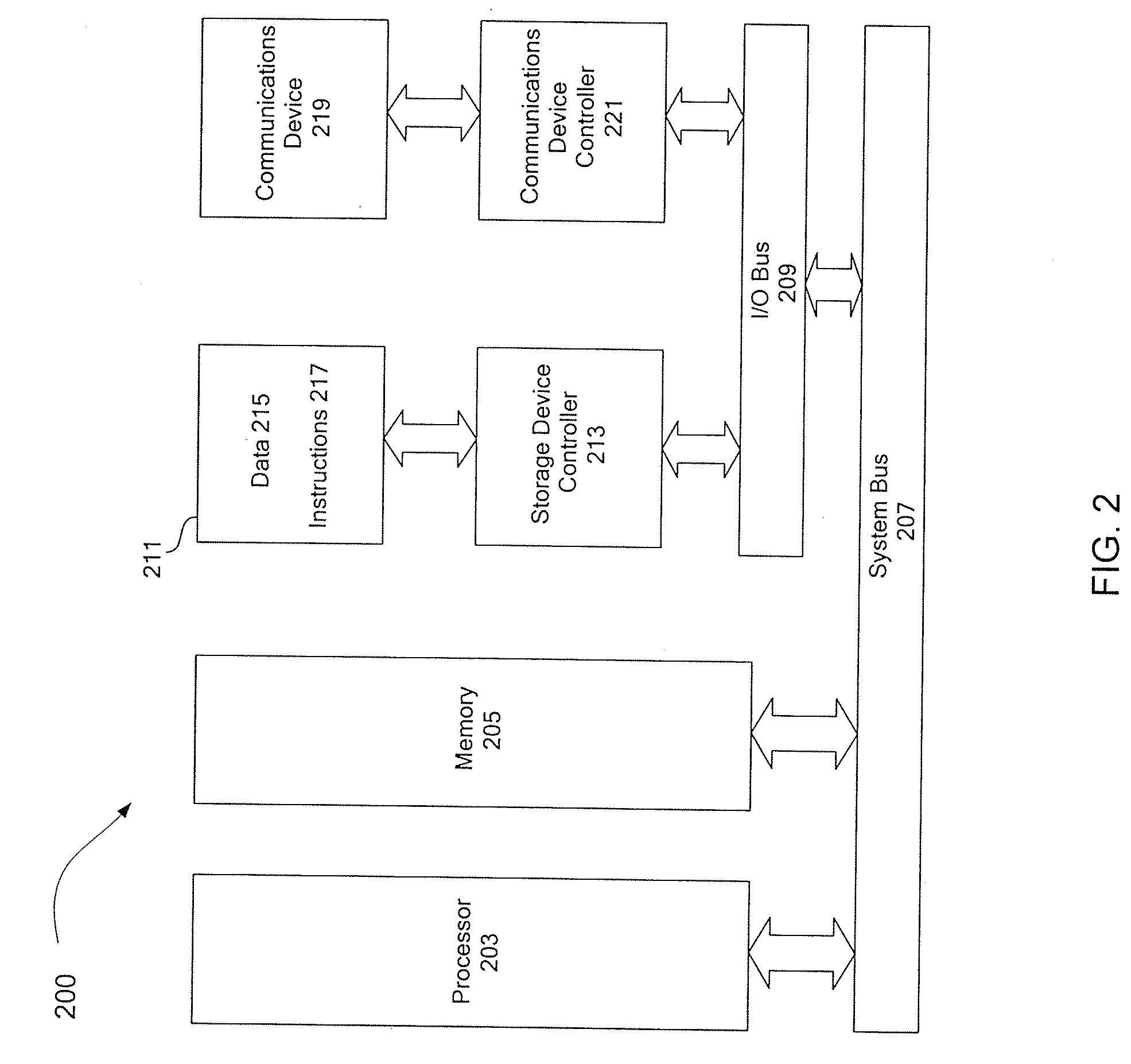
[0019]Example environments that are suitable for practicing example embodiments of the invention will now be described. Then, example embodiments of the invention will be described below. The descriptions of example environments and example embodiments are described with reference to the accompanying drawings. The example embodiments describe an apparatus, system, procedure, and computer program for allocating network bandwidth in a Max-Min fair manner.

[0020]One example environment in which example embodiments of the invention can be implemented is a fiber optic network. Fiber optic networks generally are referred to as fiber-to-the-home (FTTH), fiber-to-the-premises (FTTP), fiber-to-the-business (FTTB), fiber-to-the-node (FTTN), or fiber-to-the-curb (FTTC) networks and the like, depending on the specific application of interest. Such types of networks are also referred to herein generally as “FTTx networks”. In a typical FTTx network, equipment at a headend or central office couple...


PUM


Abstract

Allocation of an amount of available bandwidth among a plurality of users of a computer network is provided. Each user has a maximum allocation of bandwidth. Tier information of a plurality of tiers is accessed. In the tier information, users are grouped according to maximum allocation. Tier information includes a breakpoint value of each tier. The available bandwidth is allocated in one example embodiment by (1) allocating the maximum allocations to users in tiers with breakpoint values less than or equal to the amount of available bandwidth, and (2) allocating remaining available bandwidth in a fair manner among remaining users, which are users in tiers with breakpoint values greater than the amount of available bandwidth. The breakpoint value of at least one tier is a minimum amount of bandwidth that must be allocated in a Max-Min fair manner among the plurality of users such that each user in the tier receives its maximum allocation of bandwidth.

Description

BACKGROUND[0001]1. Field[0002]Example aspects of the invention relate to a procedure, system, apparatus, and program for allocating network bandwidth in a Max-Min fair manner, and, in particular, to bandwidth allocation using breakpoints based on tiers formed by grouping users according to maximum allocation information.[0003]2. Related Art[0004]In the highly-connected computing environments of the present day, multiple users often must share a limited computing resource. If total user demand for a shared resource exceeds the amount of resource available, the resource must be apportioned among the users. In the field of computer networking, for example, many methods have been developed to allocate shared network bandwidth to users in a fair and / or efficient manner. In particular, some bandwidth allocation systems apportion available bandwidth among competing users over an interval of time such that Max-Min fairness is achieved.[0005]Max-Min fairness (MMF) is a well-known fairness ob...

Claims


Application Information

Patent Timeline
Patent Type & Authority Applications(United States)
IPC IPC(8): H04J3/16
CPCH04L12/5695H04L47/828H04L47/724H04L41/0896H04L47/70
Inventor KENNEY, JOHN B.
Owner TELLABS OPERATIONS
Learn More