
LCD display with photo sensor touch function

a technology of touch function and display, which is applied in the field of liquid crystal display, can solve the problems of many errors in photosensing responsive to touch, increase the thickness, weight and additional cost of the lcd, and achieve the effect of increasing the luminance of backlight and optimal sensitivity

Active Publication Date: 2010-04-15
OPTRONIC SCI LLC
View PDF11 Cites 48 Cited by
  • Summary
  • Abstract
  • Description
  • Claims
  • Application Information

AI Technical Summary

Benefits of technology

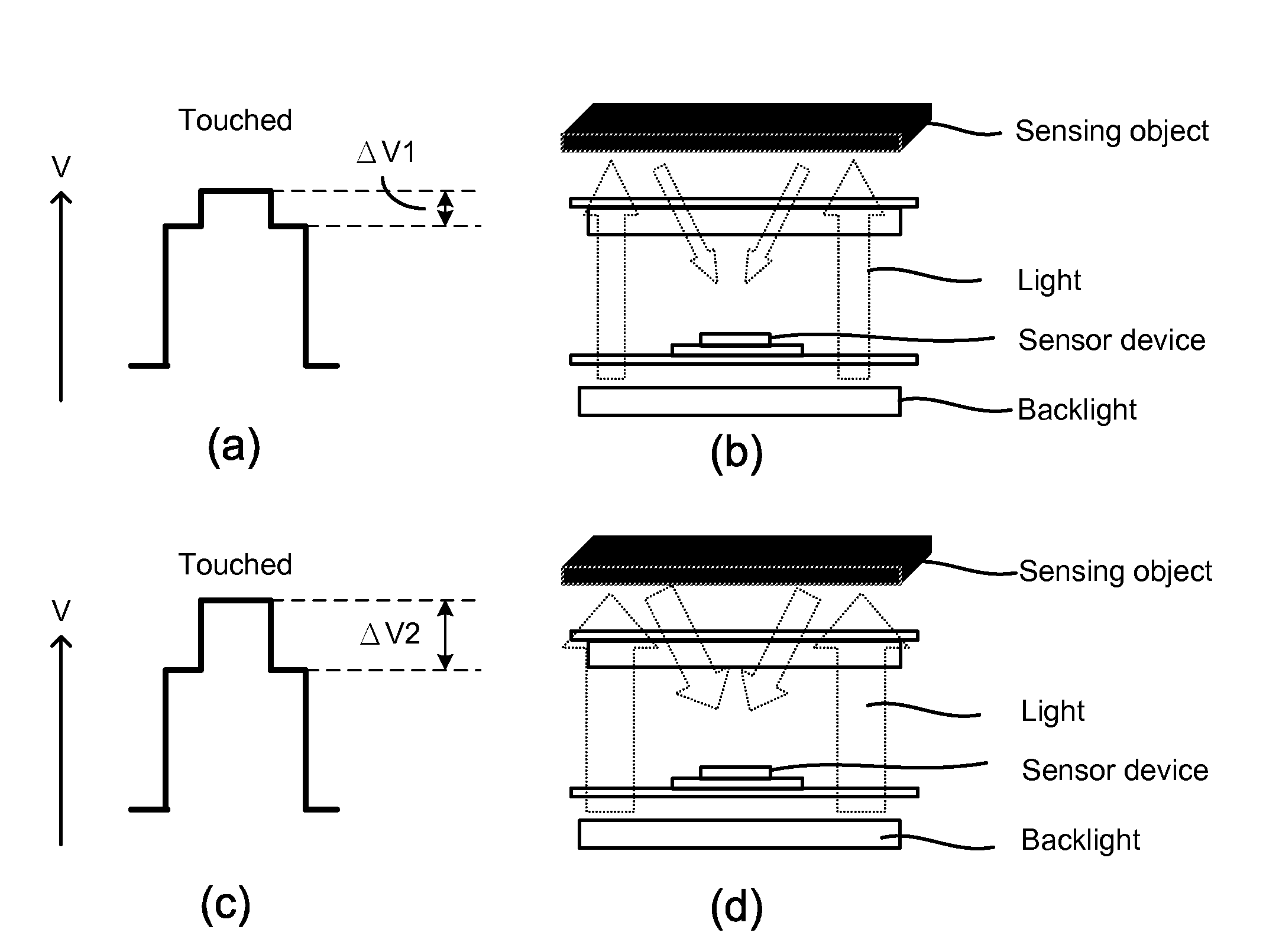
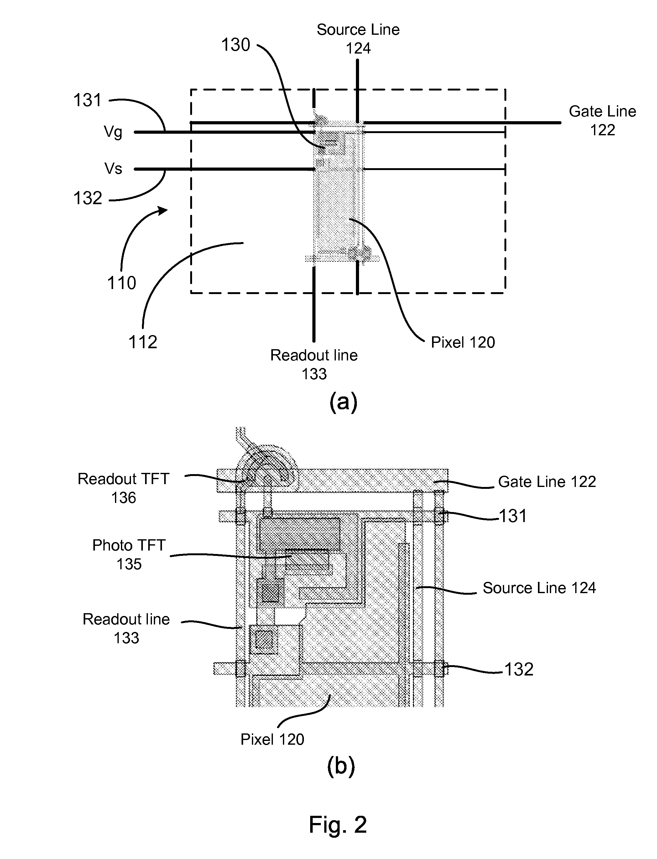
[0012]Furthermore, the method includes the steps of measuring the intensity of ambient light and generating an ambient light sensing signal corresponding to the measured intensity of the ambient light by the second photosensor member, receiving the ambient light sensing signal from the second photosensor member by the sensor controller, regulating voltages Vg and Vs according to the measured intensity of the ambient light by the sensor controller, and applying the regulated voltages Vg and Vs respectively to the gate and the source of the at least one photo transistor of the first photosensor member, so as to operate the first photosensor member at an optimal sensitivity.

Problems solved by technology

Although the touch function may be provided on an external device such as a touch screen panel to be attached to the LCD, it may increase the thickness, the weight and the additional cost of the LCD.
However, such a photosensor causes many errors in photosensing responsive to touch since an output characteristic of the photosensor varies with ambient circumstances, i.e., an intensity of ambient light, a luminance of a backlight, temperature, and so on.
Therefore, a heretofore unaddressed need exists in the art to address the aforementioned deficiencies and inadequacies.

Method used


Image

  • LCD display with photo sensor touch function
  • LCD display with photo sensor touch function
  • LCD display with photo sensor touch function

Examples


Embodiment Construction

[0033]The present invention is more particularly described in the following examples that are intended as illustrative only since numerous modifications and variations therein will be apparent to those skilled in the art. Various embodiments of the invention are now described in detail. Referring to the drawings, like numbers indicate like components throughout the views. As used in the description herein and throughout the claims that follow, the meaning of “a”, “an”, and “the” includes plural reference unless the context clearly dictates otherwise. Also, as used in the description herein and throughout the claims that follow, the meaning of “in” includes “in” and “on” unless the context clearly dictates otherwise.

[0034]The terms used in this specification generally have their ordinary meanings in the art, within the context of the invention, and in the specific context where each term is used. Certain terms that are used to describe the invention are discussed below, or elsewhere ...


PUM


Abstract

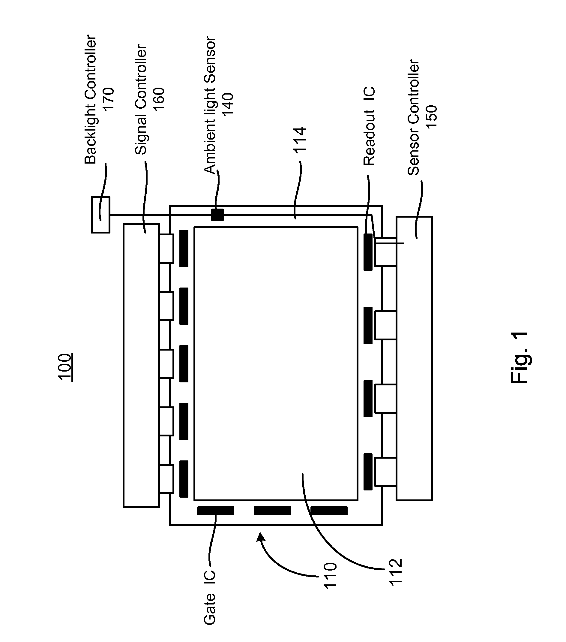
The present invention relates to a method for driving a display device having a panel having a display region and a peripheral region, a first photosensor member formed in the display region, and a second photosensor member formed in the peripheral region. In one embodiment, the method includes the steps of measuring an intensity of ambient light by the second photosensor member, and driving the first photosensor member according to the measured intensity of the ambient light, so as to sense a change of incident light caused by a touch on the display region.

Description

FIELD OF THE INVENTION[0001]The present invention relates generally to a liquid crystal display (LCD), and more particularly to an LCD that utilizes the intensity of ambient light to optimize the sensitivity of a photosensor in detection of touch information and methods of driving same.BACKGROUND OF THE INVENTION[0002]Touch sensing technology capable of providing a natural interface between an electronic system and user has found widespread applications in a variety of fields, for example, in mobile phones, personal digital assistants (PDAs), automatic teller machines (ATMs), game machines, medical devices, liquid crystal display (LCD) devices, light emitting diode (LED) devices, plasma display panel (PDP) devices, computing devices, and the like, where a user may input desired information and / or operate the electronic system through a touch sensing device associated with the electronic system.[0003]Recently, an LCD incorporating touch function has been developed. Those touch functi...

Claims


Application Information

Patent Timeline
Patent Type & Authority Applications(United States)
IPC IPC(8): G06F3/038G06F3/041
CPCG02F1/13338G02F1/13439G02F2001/13312G09G2360/144G06F3/042G09G3/3648G06F3/0412G02F1/13312
Inventor CHOU, YU-HUIHUANG, HSUEH-YINGYANG, CHUNG-HUNG
Owner OPTRONIC SCI LLC
Learn More