Brushless motor system
a brushless motor and motor technology, applied in the direction of motor/generator/converter stopper, dynamo-electric converter control, shape/form/construction of magnetic circuits, etc., can solve the problems of reducing the efficiency of the motor, increasing the size of the filter circuit, and increasing the size of the inverter itself, so as to suppress the generation of electromagnetic noise
- Summary
- Abstract
- Description
- Claims
- Application Information
AI Technical Summary
Benefits of technology
Problems solved by technology
Method used
Image

Examples
first embodiment
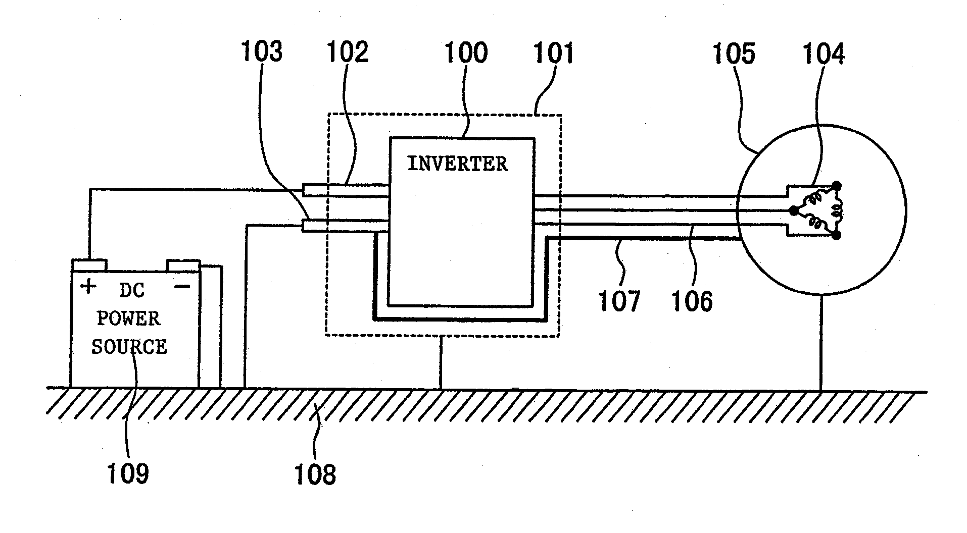
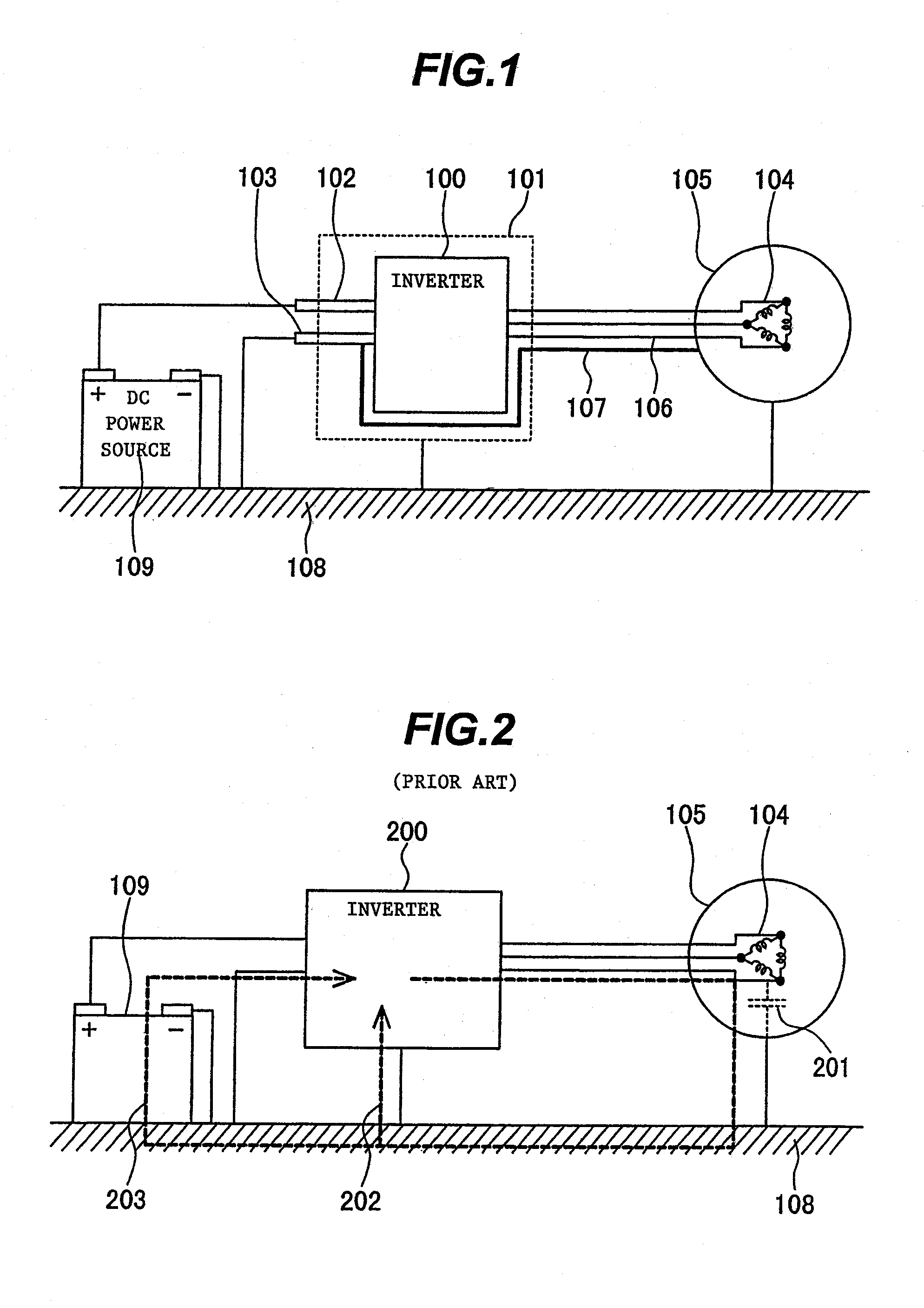
[0034]FIG. 1 shows a first embodiment of the present invention. A brushless motor system of the first embodiment comprises mainly a brushless motor, an inverter, and a direct current (DC) power source.
[0035]The inverter is constituted by an inverter circuit 100 contained in a metal housing 101. The metal housing 101 of the inverter is directly contacted with a ground 108 or electrically connected to the ground 108 through a conductor, such as a fixing member.
[0036]The brushless motor is constituted by a stator and a rotor both contained in a metal housing 105 of the motor. A current is supplied to each wire (motor winding 104) wound over the stator, to thereby generate a rotating magnetic field. The metal housing 105 of the motor is directly contacted with the ground 108 or electrically connected to the ground 108 through a conductor, such as a fixing member.
[0037]The motor windings 104 and the inverter circuit 100 are connected to each other by motor power lines 106. Also, a positi...
second embodiment
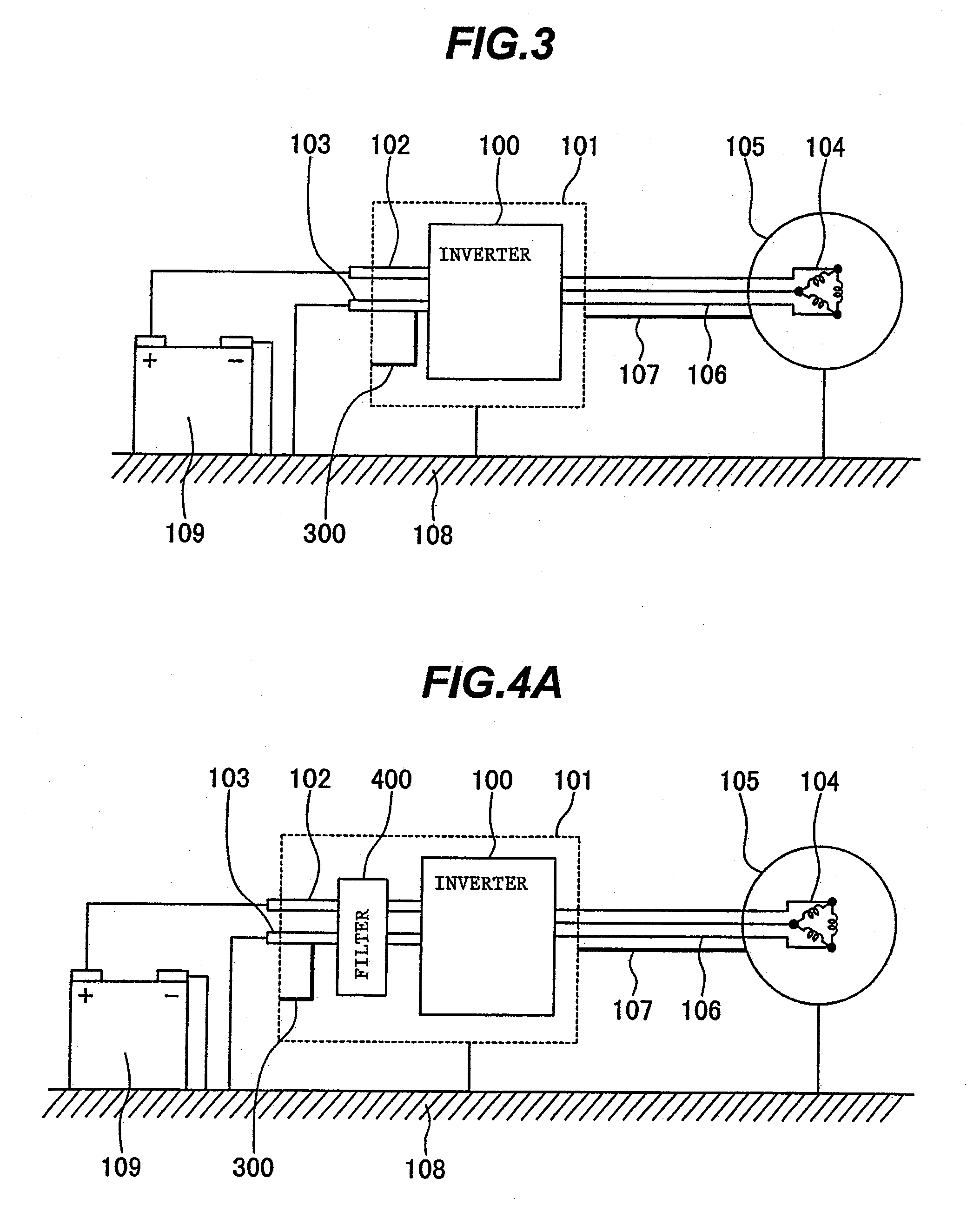
[0040]FIG. 3 shows a second embodiment of the present invention. This second embodiment is a modification of the above-described first embodiment, and the same components as those in the first embodiment are not described here.
[0041]In this second embodiment, one end of the noise return line 107 is connected to the metal housing 105 of the motor, and the other end of the noise return line 107 is connected to the metal housing 101 of the inverter. Further, the metal housing 101 of the inverter is connected to the N wiring 103 through a conductor 300. As an alternative, the N wiring 103 may be directly screwed to the metal housing 101 of the inverter in some cases without using the conductor 300. In this second embodiment, the noise current having returned from the motor side to the inverter side through the noise return line 107 reaches the N wiring 103 through the metal housing 101 of the inverter and the conductor 300, followed by returning to the inverter circuit 100.
[0042]Thus, a...
third embodiment
[0043]FIG. 4A shows a third embodiment of the present invention. This third embodiment is a modification of the above-described second embodiment, and the same components as those in the second embodiment are not described here.
[0044]In this third embodiment, a filter circuit 400 is disposed on the power source side of the inverter circuit 100. The metal housing 101 of the inverter is connected to the N wiring 103 on the power source side of the filter circuit 400 through a conductor 300. As an alternative, the N wiring 103 may be directly screwed to the metal housing 101 of the inverter without using the conductor 300.
[0045]Since this third embodiment can provide dual effects of reducing the noise current by the filter circuit 400 and returning the noise current by the noise return line 107, the generation of the common mode current can be further suppressed.
[0046]In addition, because of the combined use of both the noise return line 107 and the filter circuit 400, even when the no...
PUM
 Abstract
Description
Claims
Application Information
 - R&D
- Intellectual Property
- Life Sciences
- Materials
- Tech Scout
- Unparalleled Data Quality
- Higher Quality Content
- 60% Fewer Hallucinations
Browse by: Latest US Patents, China's latest patents, Technical Efficacy Thesaurus, Application Domain, Technology Topic, Popular Technical Reports.
© 2025 PatSnap. All rights reserved.Legal|Privacy policy|Modern Slavery Act Transparency Statement|Sitemap|About US| Contact US: help@patsnap.com