Hydrogen energy supply system using ocean current power generation

a technology of hydropower generation and energy supply system, which is applied in the direction of electrolysis components, mechanical equipment, machines/engines, etc., can solve the problems of reducing transmission loss, high construction cost, and considerable electrical energy transmission loss, and achieves the effect of simplifying system configuration and smoothing system operation

Active Publication Date: 2018-11-27
JAPAN SYST PLANNING
View PDF16 Cites 3 Cited by
  • Summary
  • Abstract
  • Description
  • Claims
  • Application Information

AI Technical Summary

Benefits of technology

[0015]A problem to be solved by the present invention lies in that there has not been a hydrogen energy supply system using ocean current power generation that can efficiently convert seawater into hydrogen energy and exploit it by using electrical energy inexpensively generated in water by many power generation facilities each having a simplified configuration with the use of ocean currents without being affected by climatic changes and that is every superior in cost performance as a whole without problems of frequency conversion of the generated electric power, transmission loss, and others.

Problems solved by technology

To transmit electrical energy generated in such a sea area to the land, a long-distance power transmission system is required, its construction costs are high, and long-distance power transmission results in considerable transmission loss of the electrical energy.
In addition, it is known that the transmission loss is lowered as a transmission voltage is increased.
However, adoption of the above-described system leads to various kinds of non-negligible power loss, e.g., loss at the time of frequency adjustment, transmission loss due to long-distance power transmission, or loss caused when power is discarded without being consumed during the night.
Further, although storing generated electrical energy in a power accumulation equipment can be considered, a large-capacity storage battery is required, and high costs must be put in, which is not cost effective.
However, in case of the hydrogen production plant according to Patent Literature 1, when a power generator is installed below a movable berth and the liquid hydrogen production plant is placed on this berth, the number of power generators to be installed is small and electric power generation of these power generators is small with respect to entire production costs including the berth, and a floor area or the like required for the seawater electrolysis device using this generated power and liquid hydrogen production and storage is overabundant.
Consequently, an increase in hydrogen gas production costs and in liquid hydrogen transmission costs is inevitable.

Method used


Image

  • Hydrogen energy supply system using ocean current power generation
  • Hydrogen energy supply system using ocean current power generation
  • Hydrogen energy supply system using ocean current power generation

Examples


examples

[0044]A hydrogen energy supply system using ocean current power generation according to an example of the present invention will now be described hereinafter in detail with reference to the drawings.

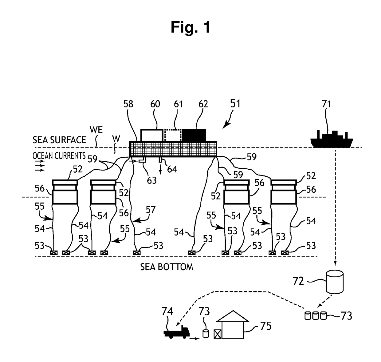
[0045]As shown in FIG. 1, a hydrogen energy supply system 51 using ocean current power generation according to this example includes: a plurality of (e.g., 10 or more) water wheel impeller type power generation devices 56 that are arranged in the sea of a sea area WE where a flow velocity of ocean currents is high, supported by a plurality of (e.g., 10 or more) first float bodies (floats) 52 respectively to float in water, moored at the bottom of sea through anchors 55 each including a cone 53 and a mooring rope 54 respectively, and use ocean currents to generate electric power; for example, a single second floating body (a mega-float) 58 that floats on the sea surface of the sea area WE and is moored at the bottom of sea through anchors 57 each including, e.g., a cone 53 and a mooring r...


PUM

PropertyMeasurementUnit
transmission voltageaaaaaaaaaa
temperatureaaaaaaaaaa
diameteraaaaaaaaaa

Abstract

A hydrogen energy supply system including 10 or more water wheel impeller type power generation devices that are supported to float in water by first floating bodies and generate electric power by using ocean currents; a second floating body on which a seawater electrolysis device, a hydrogen liquefaction device, and a liquid hydrogen tank are arranged; a hydrogen transporting ship that accommodates the liquid hydrogen stored in the liquid hydrogen tank and transports it by sea to land; an overland liquid hydrogen tank that stores the liquid hydrogen supplied from the hydrogen transporting ship; a small cylinder that accommodates the liquid hydrogen supplied from the overland liquid hydrogen tank; and a hydrogen transporting vehicle that transports the small cylinder to a consumer on land.

Description

BACKGROUND OF THE INVENTION[0001]1. Field of the Invention[0002]The present invention relates to a hydrogen energy supply system using ocean current power generation, and more particularly to a novel and breakthrough hydrogen energy supply system using ocean current power generation that uses ocean currents to generate electric power, applies electrolysis to seawater with the use of generated electrical energy to produce hydrogen energy, and supplies the produced hydrogen energy to a consumer side as liquid hydrogen.[0003]2. Description of the Related Art[0004]Approximately 70% of solar energy applied to the earth falls onto the sea, and this solar energy is mainly converted into kinetic energy of ocean currents and present.[0005]In case of generating electric power using such kinetic energy of the ocean currents, since power generation energy is proportionate to the third power of a flow velocity of ocean currents, a location with the highest flow velocity of ocean currents must be...

Claims


Application Information

Patent Timeline
Patent Type & Authority Patents(United States)
IPC IPC(8): C25B9/04C25B1/04C25B9/18
CPCC25B9/04C25B1/04C25B9/18Y02E60/366Y02E10/38Y02E60/324Y02E60/364Y02E10/28C25B9/65C25B9/70Y02E10/30Y02E60/36C01B3/042F03B13/264Y02E10/20Y02E60/32
Inventor KUMANO, KATSUYUKI
Owner JAPAN SYST PLANNING
Why Eureka
Try Eureka