
Electricity transmission cooling system

a technology of electric transmission and cooling system, which is applied in the field of cryogenic cooling system, can solve the problems of excessively high refrigeration system cost and limited length of hts cabl

Active Publication Date: 2010-04-08
AMERICAN SUPERCONDUCTOR
View PDF9 Cites 30 Cited by
  • Summary
  • Abstract
  • Description
  • Claims
  • Application Information

AI Technical Summary

Benefits of technology

The present patent is about a cooling system for high temperature superconducting (HTS) cable. The system includes a first section of HTS cable that receives a flow of coolant and allows it to flow therethrough. The coolant then flows through a first refrigeration module that divides it into multiple coolant streams. These streams flow through separate sections of the HTS cable and are combined at a second joint section. The system also includes a second refrigeration module that receives the combined coolant and performs re-cooling and re-pressurization on it. The system is designed to maintain a consistent operating pressure throughout each section of the HTS cable. The technical effects of the cooling system include improved cooling efficiency, reduced coolant flow resistance, and improved stability of the coolant temperature.

Problems solved by technology

Unfortunately, as a result of existing cooling system designs, the length of an HTS cable may be limited due to limited pressure head and cooling power produced by a single cooling station.
These systems may also require that refrigeration systems be tailored to individual cable projects, which may result in an excessively high refrigeration system cost.

Method used


Image

  • Electricity transmission cooling system
  • Electricity transmission cooling system
  • Electricity transmission cooling system

Examples


Embodiment Construction

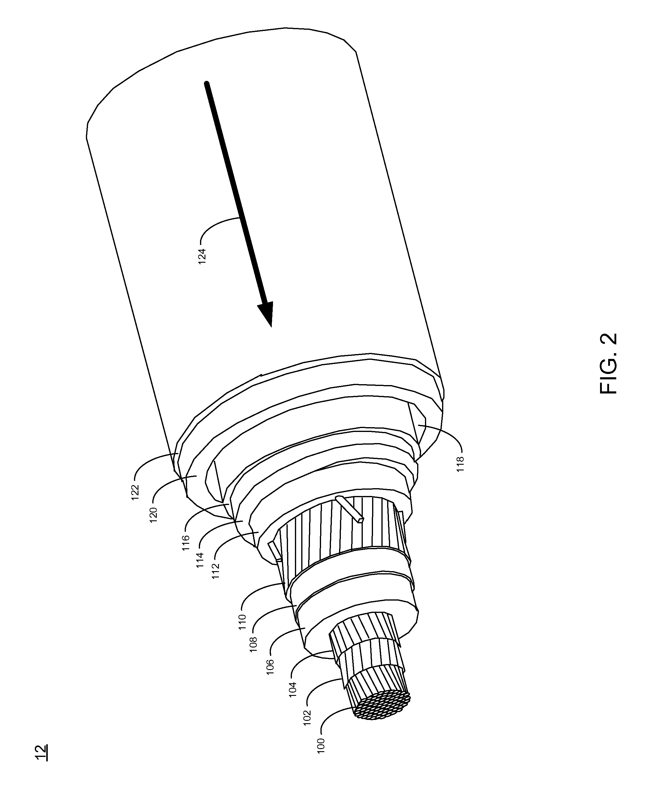
[0028]Referring to FIG. 1, a portion of a utility power grid 10 may include a high temperature superconductor (HTS) cable 12. HTS cable 12 may be hundreds or thousands of meters in length and may provide a relatively high current / low resistance electrical path for the delivery of electrical power from generation stations (not shown) or imported from remote utilities (not shown).

[0029]The cross-sectional area of HTS cable 12 may only be a fraction of the cross-sectional area of a conventional copper core cable and may be capable of carrying the same amount of electrical current or more. As discussed above, within the same cross-sectional area, an HTS cable may provide three to five times the current-carrying capacity of a conventional AC cable; and up to ten times the current-carrying capacity of a conventional DC cable. As HTS technology matures, these ratios may increase.

[0030]As will be discussed below in greater detail, HTS cable 12 includes HTS wire, which may be capable of hand...


PUM


Abstract

A cooling system includes a first section of high temperature superconducting (HTS) cable configured to receive a first flow of coolant and to permit the first flow of coolant to flow therethrough. The system may further include a second section of high temperature superconducting (HTS) cable configured to receive a second flow of coolant and to permit the second flow of coolant to flow therethrough. The system may further include a cable joint configured to couple the first section of HTS cable and the second section of HTS cable. The cable joint may be in fluid communication with at least one refrigeration module and may include at least one conduit configured to permit a third flow of coolant between said cable joint and said at least one refrigeration module through a coolant line separate from said first and second sections of HTS cable. Other embodiments and implementations are also within the scope of the present disclosure.

Description

GOVERNMENT RIGHTS[0001]This invention was made with Government support under Agreement No.: DE-FC26-07NT43240. The Government has certain rights in the invention.TECHNICAL FIELD[0002]This disclosure relates to cooling systems and, more particularly, to cryogenic cooling systems for high temperature superconductor (“HTS”) devices, in particular HTS power cables.BACKGROUND[0003]Superconductivity refers to a state of materials in which the electrical resistance becomes zero when the material is cooled to a sufficiently low temperature, referred to as the critical temperature. One type of superconductor, referred to as a high temperature superconductor (HTS), has a critical temperature in excess of the boiling point of liquid nitrogen of 77° K. at atmospheric pressure.[0004]The use of superconductive materials and, in particular, superconducting cables, is advantageous because of the elimination of resistive losses. As a result, superconducting cables are being designed, built and teste...

Claims


Application Information

Patent Timeline
Patent Type & Authority Applications(United States)
IPC IPC(8): H01L39/02F25B45/00H10N60/00F25D23/00H10N60/80
CPCY02E40/647H01B12/16H02G15/34Y02E40/648Y02E40/60H10N60/00H10N60/80
Inventor YUAN, JIEMAGUIRE, JAMES
Owner AMERICAN SUPERCONDUCTOR
Learn More