
Planar lightwave circuit

a lightwave circuit and circuit technology, applied in the field of planar lightwave circuits, can solve the problems of adding significant to the overall cost of the system, introducing additional insertion loss of wdm signals,

Active Publication Date: 2010-04-08
INFINERA CORP
View PDF11 Cites 7 Cited by
  • Summary
  • Abstract
  • Description
  • Claims
  • Application Information

AI Technical Summary

Problems solved by technology

Equipment in both transmit and receives ends of the WDM system often include discrete components, which can introduce additional insertion loss to the WDM signals and can add significantly to the overall cost of the system.

Method used


Image

  • Planar lightwave circuit
  • Planar lightwave circuit
  • Planar lightwave circuit

Examples


Embodiment Construction

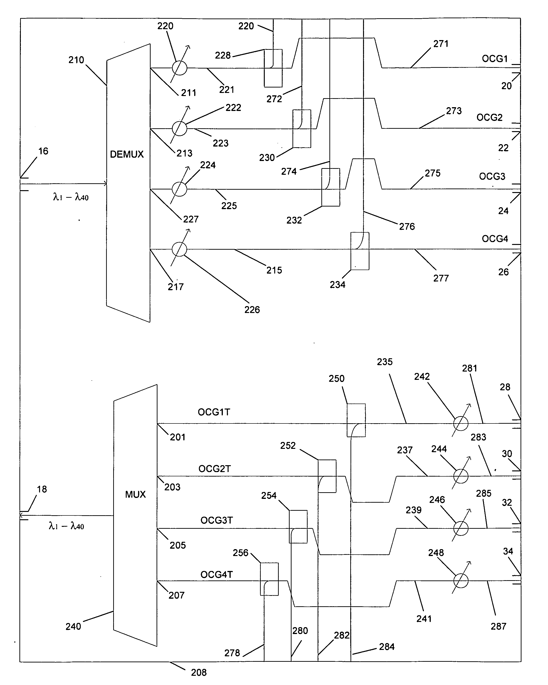
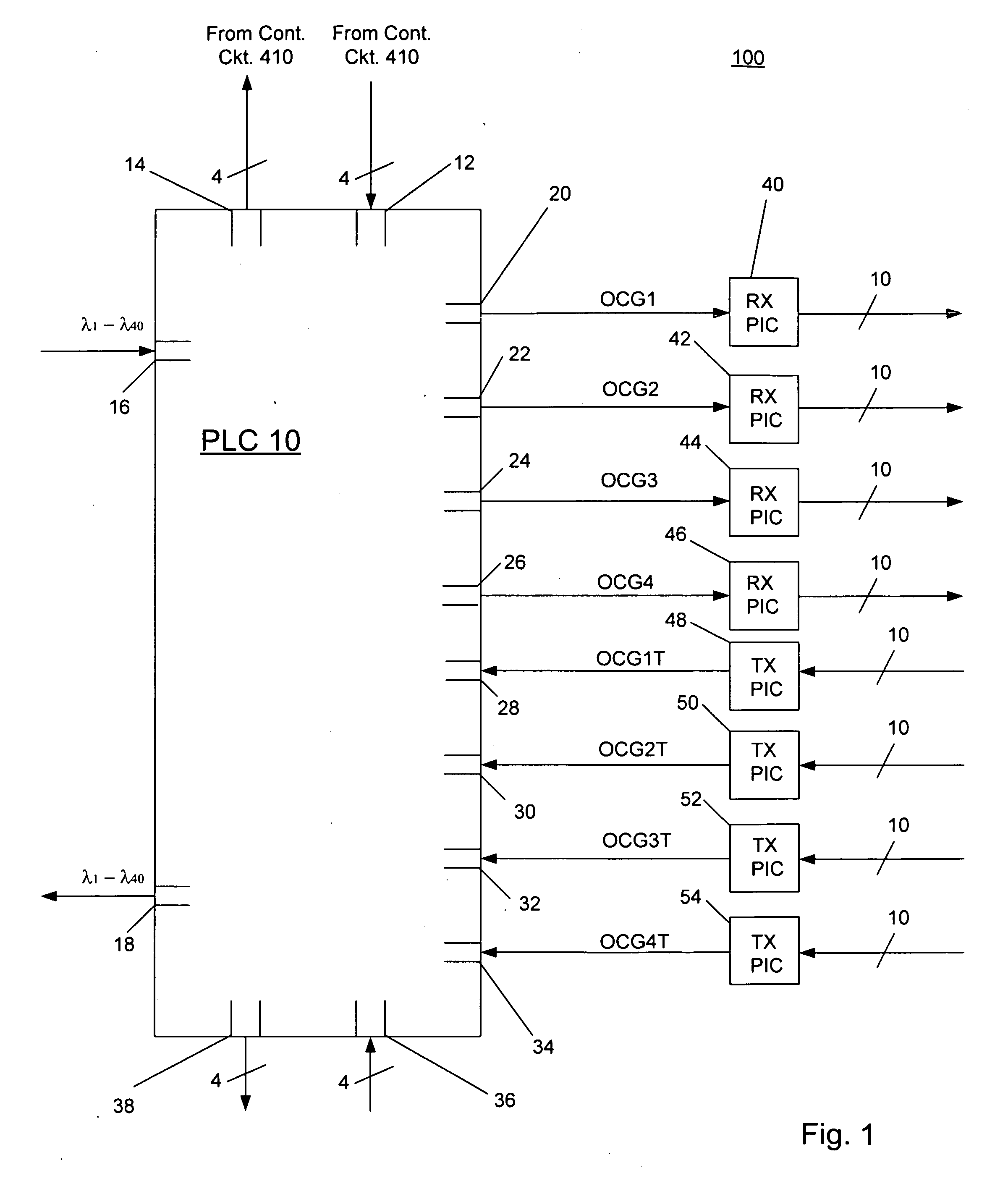
[0013]Consistent with the present disclosure optical interleaver and deinterleaver circuits are integrated onto a substrate. The inputs to the interleaver and the outputs of the deinterleaver are each coupled to a corresponding variable optical attenuator (VOA) and optical tap, which are also provided on the substrate. The optical taps supply a portion of the output of each VOA to a corresponding photodetector. A control circuit, which is coupled to the photodetector, in turn, supplies a control signal to each VOA based on the output of the photodetector. Accordingly, optical multiplexing and demultiplexing components, as well as monitoring and power regulating components are provided on the same chip. Such a chip may be compact and relatively inexpensive compared to optical multiplexer and demultiplexer equipment including discrete components.

[0014]Reference will now be made in detail to the present exemplary embodiments, which are illustrated in the accompanying drawings. Wherever...


PUM


Abstract

Consistent with the present disclosure optical interleaver and deinterleaver circuits are integrated onto a substrate. The inputs to the interleaver and the outputs of the deinterleaver are each coupled to a corresponding variable optical attenuator (VOA) and optical tap, which are also provided on the substrate. The optical taps supply a portion of the output of each VOA to a corresponding photodetector. A control circuit, which is coupled to the photodetector, in turn, supplies a control signal to each VOA based on the output of the photodetector. Accordingly, optical multiplexing and demultiplexing components, as well as monitoring and power regulating components are provided on the same chip. Such a chip may be compact, relatively inexpensive, and has reduced power consumption compared to optical multiplexer and demultiplexer equipment including discrete components.

Description

[0001]This application claims the benefit under 35 U.S.C. §119(e) of U.S. Provisional Patent Application No. 61 / 059,676, the entire contents of which are incorporated herein by reference.BACKGROUND[0002]In a wavelength division multiplexed (WDM) optical communication system, multiple optical signals, each at a different wavelength, are typically combined onto an optical fiber. In order to multiplex these signals onto the fiber, various optical components, such as optical filters and / or optical combiners, are provided at a transmit end of a WDM system. At a receive end of the system, additional components are provided that separate the optical signals according to wavelength and convert the optical signals into corresponding electrical signals. At both transmit and receive ends of the WDM system, equipment may be provided to monitor the power levels of each of the optical signals, for example.[0003]Equipment in both transmit and receives ends of the WDM system often include discrete ...

Claims


Application Information

Patent Timeline
Patent Type & Authority Applications(United States)
IPC IPC(8): H04J14/02
CPCH04J14/02H04J14/0307
Inventor MITCHELL, MATTHEW L.VAN LEEUWEN, MICHAEL
Owner INFINERA CORP
Learn More