Position sensor

a position sensor and noncontact technology, applied in the direction of converting the output of the sensor electrically/magnetically, instruments, dynamo-electric components, etc., can solve the problems of failure and temperature drift compensation of the throttle position sensor using the failure of the detection accuracy of the magnetic resistance element, and the inability to detect continuous positions, etc., to achieve the effect of increasing the overall inductance of the entire coil pole, reducing the over manufacturing cost of the position sensor

Active Publication Date: 2010-04-08
AMITEQ
View PDF5 Cites 12 Cited by
  • Summary
  • Abstract
  • Description
  • Claims
  • Application Information

AI Technical Summary

Benefits of technology

[0007]According to the present invention, a plurality of layers of flat coils are stacked on each other and connected in series with each other to form a single coil pole, and thus, even through the number of turns of each of the flat coils is limited with the coil diameter of the flat coil reduced, an additive combination of the inductance of the stacked flat coils can increase the overall inductance of the entire coil pole. As a consequence, the impedance variation of the coil pole, which depends on relative positional relationship between the coil section and the magnetism-responsive member responsive to a position to be detected (object of detection), can be increased, so that the coil output signal responsive to the position to be detected can be increased in level. As a result, it is possible to achieve position detection with an increased accuracy despite a small-size / thin coil structure. Further, the use of the flat coils (printed coils) can lower the over manufacturing cost of the position sensor.
[0008]In one embodiment, the magnetism-responsive member has a limited width in a direction traversing a direction of the relative displacement, and the width has a shape gradually increasing or gradually decreasing along the direction of the relative displacement. The magnetism-responsive member is disposed so that the widest portion of the magnetism-responsive member is narrower than a width of the flat coils of the coil pole in such a manner that even the widest portion does not project beyond the width of the flat coils in the direction traversing the direction of the relative displacement. With such an arrangement, it is possible to eliminate a detection error due to assembly errors, such as a radial error, or mechanical wobble in the direction traversing the direction of the relative displacement.
[0009]In one embodiment, two magnetism-responsive members of the same construction are disposed to sandwich the coil section in an axial direction of the flat coils. With such an arrangement, it is possible to eliminate a detection error due to assembly errors, such as a thrust error, or mechanical wobble in the axial direction of the coils.

Problems solved by technology

However, the throttle position sensor comprising a potentiometer, disclosed in Patent Literature 1, has problems related to life of use, failure and temperature drift of a resistance element because it is of a non-contact type.
Further, the throttle position sensor using a magnetic resistance element, disclosed in Patent Literature 2, is problematic in terms of detection accuracy and temperature drift compensation.
Furthermore, the position sensor using a HALL element, disclosed in Patent Literature 3, is disadvantageous in that it is not suited for continuous position detection.
Although sheet-shaped flat coils have also been known, it has not been possible to construct a practical position sensor because sufficient inductance can not be obtained with such a sheet-shaped flat coil.

Method used


Image

  • Position sensor
  • Position sensor
  • Position sensor

Examples


Embodiment Construction

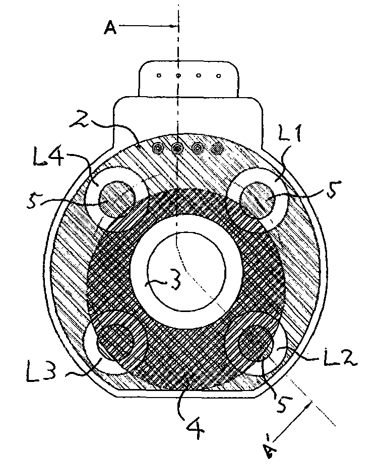
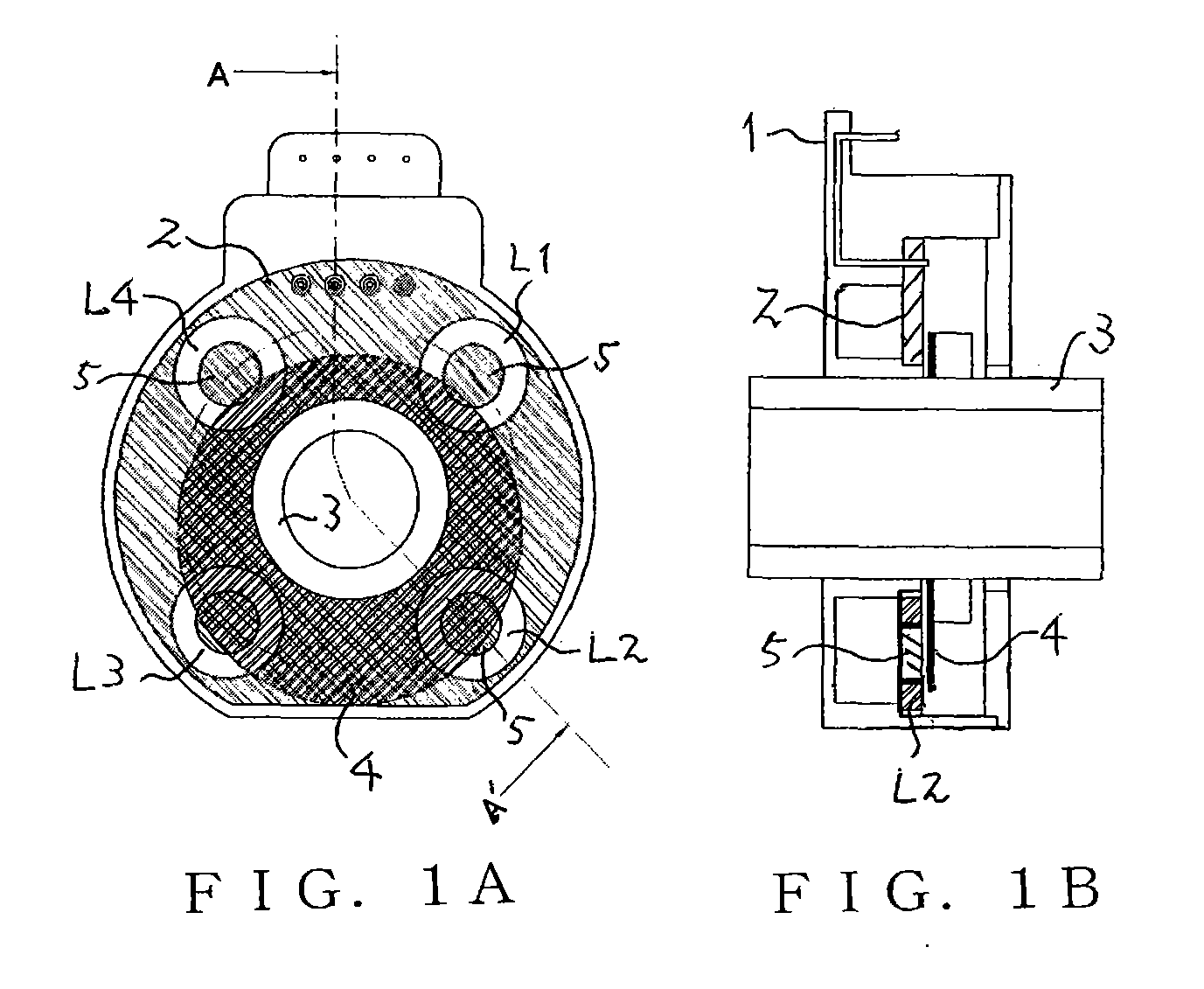
[0022]FIG. 1A is a front view schematically showing a construction of a rotary-type position sensor, FIG. 1B is a schematic sectional view taken along the A-A′ line of FIG. 1A. This rotary-type position sensor comprises a stator section and a rotor section. The stator section includes a coil section 2 mounted in a sensor case 1, and the rotator section includes a rotor shaft 3 rotatably mounted to the sensor case 1 and a rotor 4 that comprises a magnetism-responsive member mounted on the rotor shaft 3 so that it can be rotationally displaced together with the rotor shaft 3.

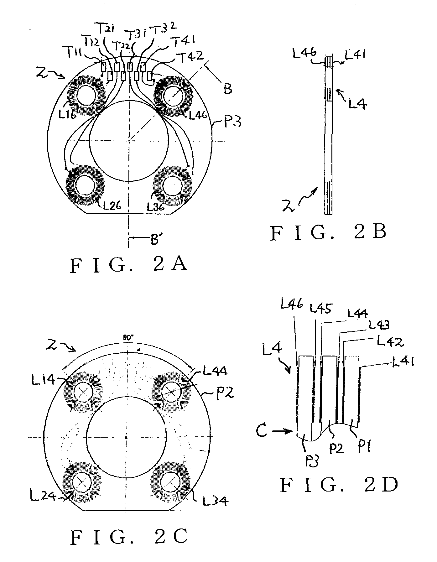
[0023]The coil section 2 includes a plurality of coil poles L1, L2, L3 and L4 disposed at predetermined intervals along the circumference of the coil section 2. In the instant embodiment, four coil poles L1, L2, L3 and L4 are provided at 90° intervals, so that rotational positions over one full rotation are detectable. However, the number and intervals of the coil poles are not so limited. In the coil section 2, e...


PUM

PropertyMeasurementUnit
electrical angleaaaaaaaaaa
mechanical angleaaaaaaaaaa
magnetism-responsiveaaaaaaaaaa

Abstract

A plurality of layers of flat coils are stacked and connected in series with each other to form a single coil pole, and the coil pole is energized by an A.C. signal. Magnetism-responsive member, provided to be opposed to the coil pole in a non-contact manner, is displaced relative to the coil pole, so that correspondency, to the coil section, of the magnetism-responsive member varies in response to variation in the relative position and thus impedance variation occurs in the coil pole. Position detection signal is provided on the basis of an output signal, responsive to the impedance variation, taken out from the coil pole.

Description

[0001]This application is a U.S. National Phase Application of PCT International Application PCT / JP2006 / 312636 filed on Jun. 23, 2006.TECHNICAL FIELD[0002]The present invention relates to a high-accuracy, non-contact type position sensor which is small in size and yet capable of producing great output levels. For example, the present invention relates to a position sensor which is suited for use as a throttle position sensor of an internal combustion engine and as a position sensor for detecting mechanical movement of a part of an automotive vehicle, and which can be used for various other applications.BACKGROUND ART[0003]Patent Literature 1 (Japanese Utility Model Application Laid-open Publication No. SHO-59-41708) discloses a throttle position sensor comprising a contact-sliding type variable resistor (potentiometer). Patent Literature 2 (Japanese Patent Application Laid-open Publication No. HEI-2-298802) discloses a non-contact type throttle position sensor using a magnetic resis...

Claims


Application Information

Patent Timeline
Patent Type & Authority Applications(United States)
IPC IPC(8): G01D5/22G01D5/20H01F5/00
CPCG01D5/2013H02K24/00H02K11/0031G01D5/2216H02K11/225
Inventor GOTO, ATSUTOSHI
Owner AMITEQ
Why Eureka
Try Eureka