Gasket For A Valve In An Internal Combustion Engine

a technology for internal combustion engines and gaskets, which is applied in the direction of valve operating devices/release devices, machines/engines, mechanical devices, etc., can solve the problems of deterioration in engine efficiency, excessive consumption of oil itself, and drop in the performance of motor vehicle catalytic converters, so as to reduce the build-up of tension and increase the curvature radius

Inactive Publication Date: 2010-04-08
CORCOS IND DI FREUDENBERG & COSSO
View PDF7 Cites 2 Cited by
  • Summary
  • Abstract
  • Description
  • Claims
  • Application Information

AI Technical Summary

Benefits of technology

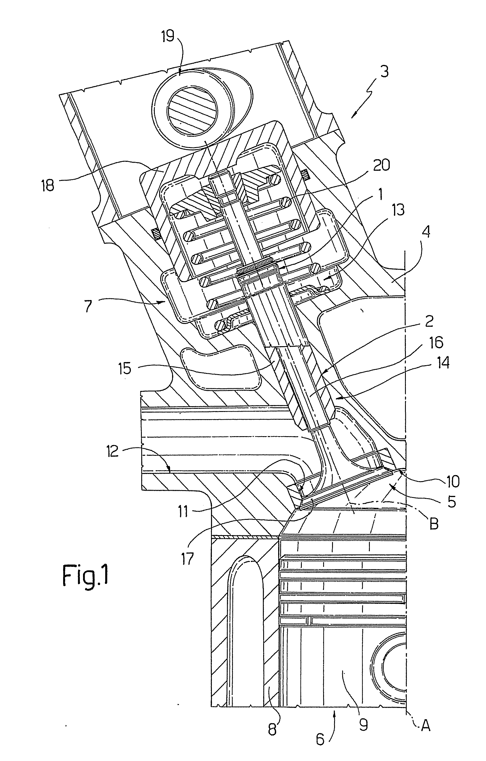
[0009]The gaskets of the above described type are widely used in all internal combustion engines to control the amount of lubricating oil that flows from the distribution area towards the combustion chambers. An excessive flow of lubricating oil causes a deterioration in the efficiency of the engine and a drop in the performance of the motor vehicle catalytic converter as well as an evident excessive consumption of the oil itself. On the other hand, an insufficient flow determines an increase in the wear and the noise of the valves together with the occurrence of local temperature peaks. These phenomena may determine a premature damage of the valves following the seizure of the rod of the valves themselves within the guide element.
[0013]The present disclosure provides a gasket for a valve in an internal combustion engine, which overcomes the drawbacks related to the gaskets of the known and above specified type in a simple and cost-effective manner.
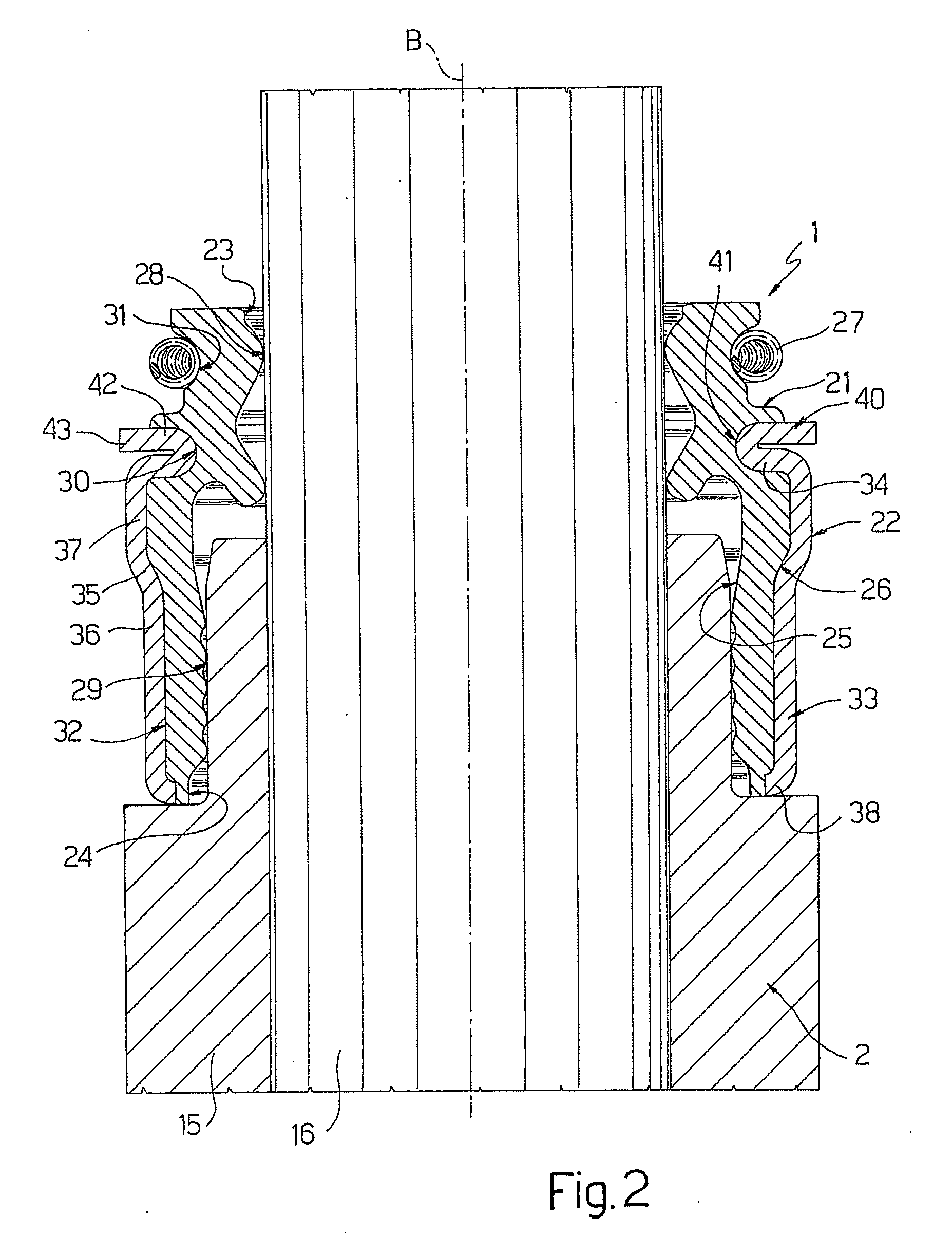
[0050]The portion 33 can display an intermediate segment 35 having increasing radial size towards the portion 34 so as to reduce the size of the elastomeric element 21.
[0061]Specifically, the presence on the portion 34 of the support element 22 which is drowned in the elastomeric element 21 of a further portion 40 folded on the portion 34 itself so as to form a rounded edge 41 allows to obtain an increase in the curvature radius of the profile of the notch 30 which houses the portions 34 and 40 of the support element 22 with respect to the known solutions; in this manner, it is possible to reduce the build-up of the tension within the elastomeric element 21 when the external stress is the same.

Problems solved by technology

An excessive flow of lubricating oil causes a deterioration in the efficiency of the engine and a drop in the performance of the motor vehicle catalytic converter as well as an evident excessive consumption of the oil itself.
On the other hand, an insufficient flow determines an increase in the wear and the noise of the valves together with the occurrence of local temperature peaks.
These phenomena may determine a premature damage of the valves following the seizure of the rod of the valves themselves within the guide element.

Method used


Image

  • Gasket For A Valve In An Internal Combustion Engine
  • Gasket For A Valve In An Internal Combustion Engine
  • Gasket For A Valve In An Internal Combustion Engine

Examples


Embodiment Construction

[0020]Example embodiments will now be described more fully with reference to the accompanying drawings.

[0021]Example embodiments are provided so that this disclosure will be thorough, and will fully convey the scope to those who are skilled in the art. Numerous specific details are set forth such as examples of specific components, devices, and methods, to provide a thorough understanding of embodiments of the present disclosure. It will be apparent to those skilled in the art that specific details need not be employed, that example embodiments may be embodied in many different forms and that neither should be construed to limit the scope of the disclosure. In some example embodiments, well-known processes, well-known device structures, and well-known technologies are not described in detail.

[0022]The terminology used herein is for the purpose of describing particular example embodiments only and is not intended to be limiting. As used herein, the singular forms “a,”“an,” and “the” ...


PUM


Abstract

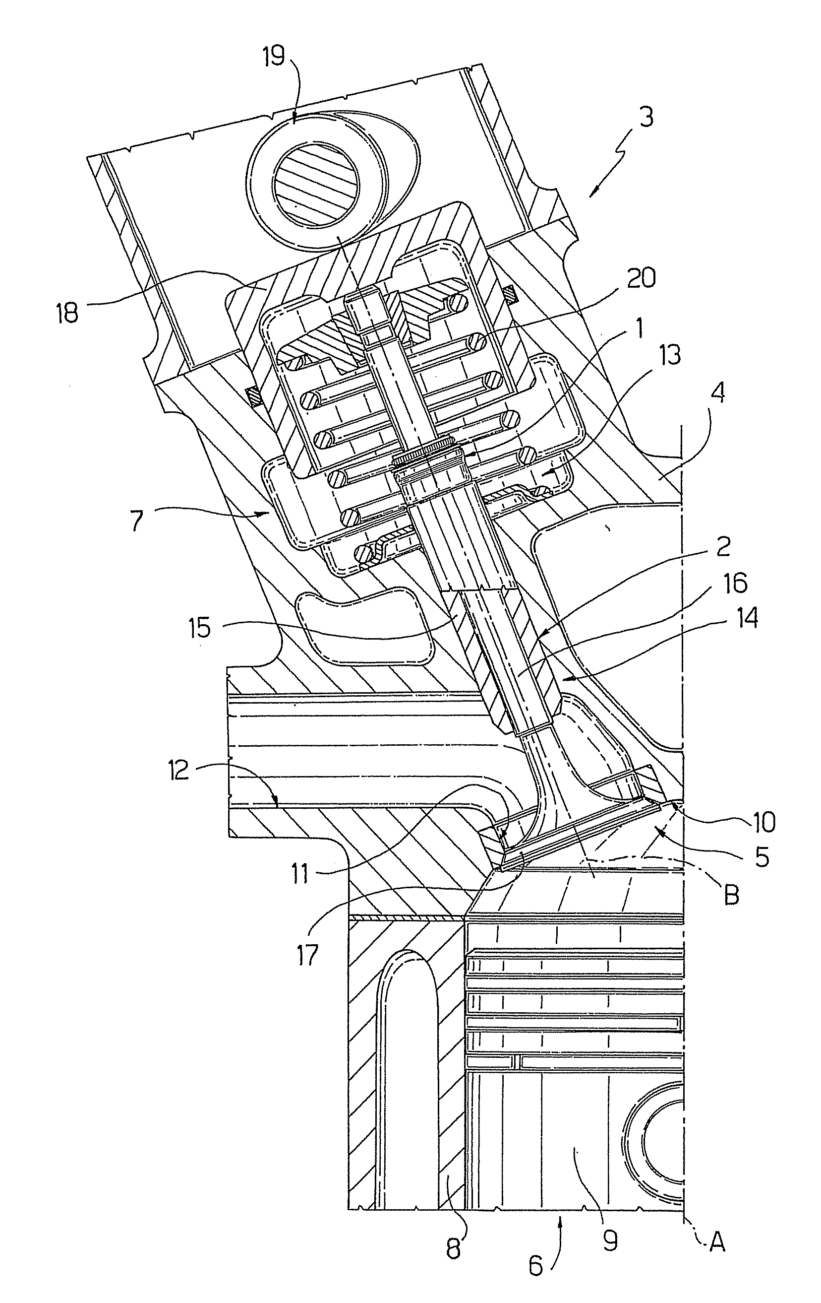
A gasket for a valve in an internal combustion engine is provided with a support element having a tubular configuration according to an axis and coaxially mounted on the valve. An elastically deformable element is interposed between the support element and the valve. The support element includes a first portion elongated according to the above mentioned axis, and a second portion extending from the first portion in a direction transversal to the axis, at least partially housed in an annular seat of the elastically deformable element and having its radially outermost end connected to the first portion itself. The support element comprises a third portion extending from the radially innermost end of the second portion and folded on the second portion itself so as to generate, in the folding area, a rounded edge cooperating with the annular seat of the elastically deformable element.

Description

CROSS-REFERENCE TO RELATED APPLICATIONS[0001]This application is a continuation of U.S. patent application Ser. No. 11 / 961,389, filed on Dec. 20, 2007, which claims the benefit of European Patent Application No. EP06425889.0, filed Dec. 29, 2006, the disclosures of which are incorporated herein by reference.FIELD[0002]The present disclosure relates to a gasket for a valve in an internal combustion engine.BACKGROUND AND SUMMARY[0003]This section provides background information related to the present disclosure which is not necessarily prior art.[0004]There are known internal combustion engines for motor vehicles comprising a head bearing one or more cylinders, within which the work cycle is carried out, and which are placed in communication with respective combustion chambers of the engine itself. On the above mentioned head, there are further obtained appropriate seats intended to let the combustion chamber communicate with ducts adapted to supply a mixture of unburnt fuel and air t...

Claims


Application Information

Patent Timeline
Patent Type & Authority Applications(United States)
IPC IPC(8): F02F11/00
CPCF01L3/08
Inventor SCARANO, FRANCESCO
Owner CORCOS IND DI FREUDENBERG & COSSO
Why Eureka
Try Eureka