
Lifting mechanism for an exercise apparatus

a lifting mechanism and exercise technology, applied in the direction of belts/chains/gearings, gymnastic exercises, belts/chains/gearings, etc., can solve the problems of increasing production costs in addition to the increase of weight, damage with fractures, etc., and achieves high strength, high strength, and high strength. material

Inactive Publication Date: 2010-04-08
KO CHEN HUI
View PDF19 Cites 5 Cited by
  • Summary
  • Abstract
  • Description
  • Claims
  • Application Information

AI Technical Summary

Benefits of technology

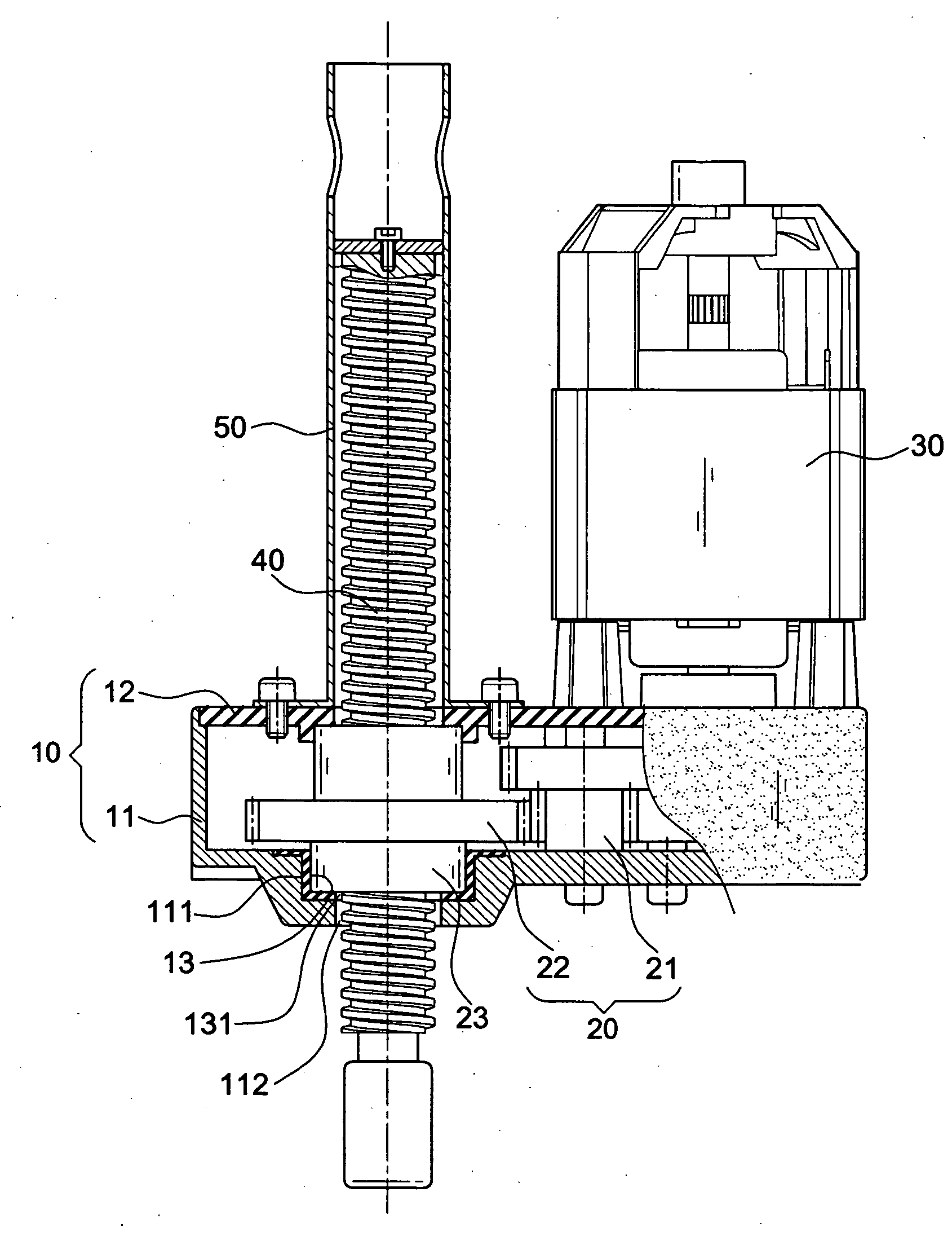
[0006]An object of the invention is to provide a lifting mechanism for an exercise apparatus that includes a housing with portion subject to force being made of high strength material. Moreover, the high strength material is applied to the internal wall of the plastic housing in such a way that the internal transmission gear is in contact of the high strength material rather than in contact of the housing. As a result, the plastic housing can achieve the effect of reducing weight. Meanwhile, the strength can be maintained such that no fracture takes place. Furthermore, a prolonged service life is ensured.
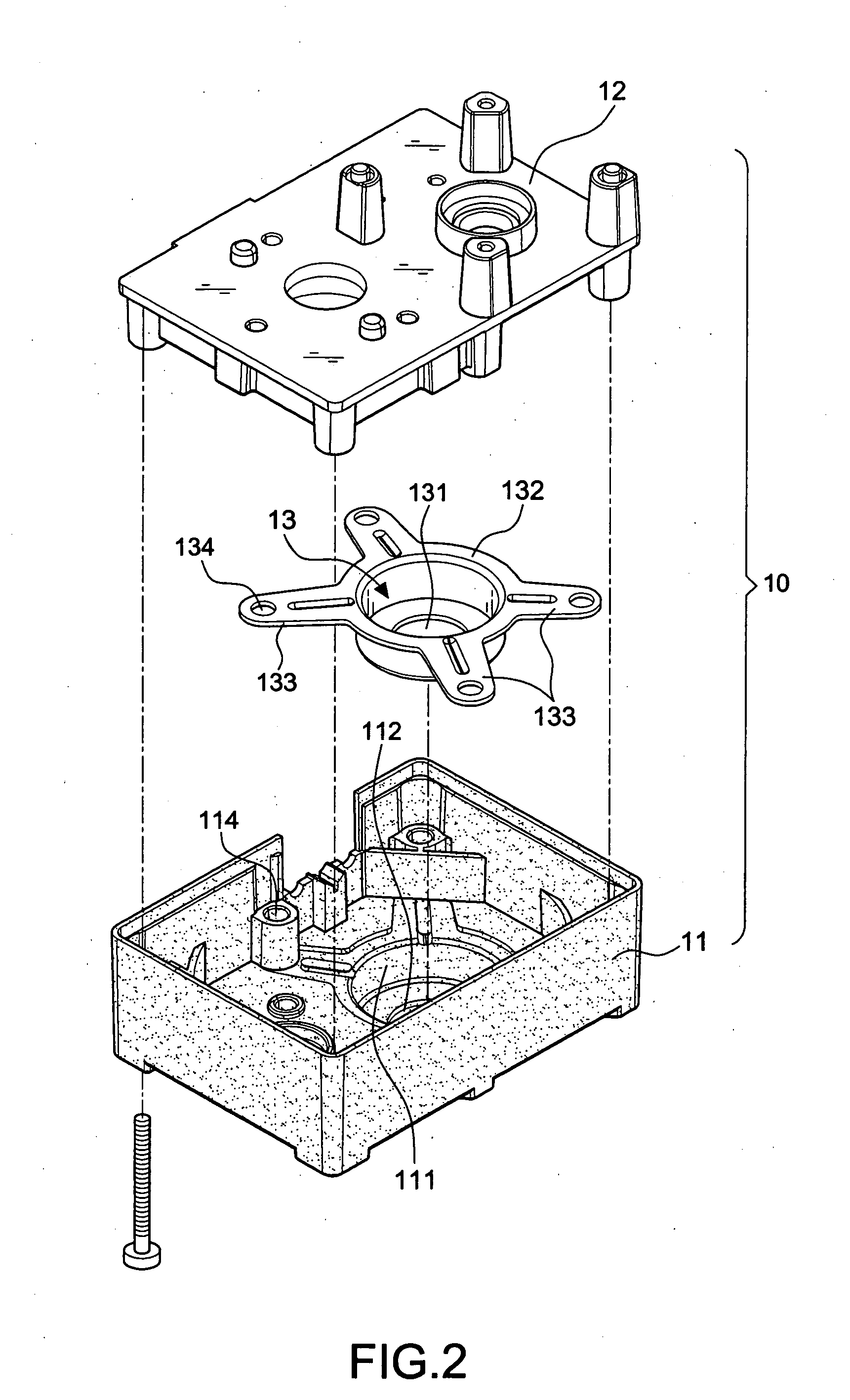
[0007]In order to achieve the above-mentioned object, a lifting mechanism for an exercise apparatus frame base includes a housing made of lightweight material with a positioning cavity having a through hole. A covering cap having a circular internal rim is integrally formed within the positioning cavity and made by high strength material an injection molding process is performed. The bottom of the covering cap includes an axle hole corresponding to the through hole. The top of the covering cap has an opening with a positioning flange extending outwards. In this way, the drawback that the inside of the conventional plastic housing is easily damaged by the transmission gear can be eliminated. As a result, the weight can be minimized and the strength can be maintained.

Problems solved by technology

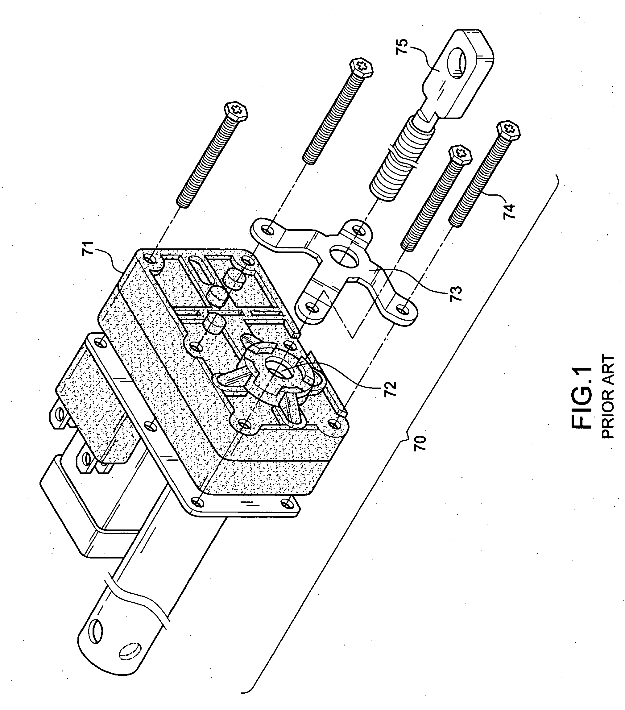
The reduction gear of the conventional transmitting and lifting mechanism is completely made of metal by the casting process, thereby considerably increasing the production cost in addition to the increase of weight.
However, when a driving gear (not shown) disposed within the plastic housing 71 drives a spindle 75 into rotation, a threaded sleeve will generate the torsional type friction acting on the internal wall of the housing 71, thereby leading to damage with fracture.

Method used


Image

  • Lifting mechanism for an exercise apparatus
  • Lifting mechanism for an exercise apparatus
  • Lifting mechanism for an exercise apparatus

Examples


Embodiment Construction

[0015]First of all, referring to FIGS. 2 through 5, a lifting mechanism for an exercise apparatus in accordance with the invention includes a housing 10. The housing 10 consists of a frame base 11 with an opening surface and a cover plate 12. The frame base 11 is made of lightweight material, such as plastic, acrylonitrile butadiene styrene (ABS), etc. The frame base 11 includes a positioning cavity 111 with a through hole 112. A covering cap 13 is integrally formed within the positioning cavity 111. Meanwhile, the covering cap 13 is made by high strength material such as steel plates. Moreover, the covering cap 13 has a circular internal rim. The bottom of the covering cap 13 includes an axle hole 131 corresponding to the through hole 112. The top of the covering cap 13 has an opening with a positioning flange 132 extending outwards. At least one positioning claw 133 is extended from the positioning flange 132. The cover plate 12 is also formed by high strength material such as ste...


PUM


Abstract

A lifting mechanism for an exercise apparatus frame base includes a housing made of lightweight material with a positioning cavity having a through hole. A covering cap having a circular internal rim is integrally formed within the positioning cavity and made by high strength material an injection molding process is performed. The bottom of the covering cap includes an axle hole corresponding to the through hole. The top of the covering cap has an opening with a positioning flange extending outwards. In this way, the drawback that the inside of the conventional plastic housing is easily damaged by the transmission gear can be eliminated. As a result, the weight can be minimized and the strength can be maintained.

Description

BACKGROUND OF THE INVENTION[0001]1. Field of the Invention[0002]The invention relates to a lifting mechanism for an exercise apparatus, and more particularly, to a circular covering cap 13 the portion of which is not subject to force being made of lightweight material while the portion of which is subject to force being made of high strength material.[0003]2. Description of the Related Art[0004]Most of the conventional exercise apparatuses include a lifting mechanism to adjust its inclination relative to a horizontal plane. In order to facilitate the operation thereof, a motor is employed to drive a reduction gearset for imparting rotational motion to a lifting element. In this way, a desired angle is achieved.[0005]The reduction gear of the conventional transmitting and lifting mechanism is completely made of metal by the casting process, thereby considerably increasing the production cost in addition to the increase of weight. In order to avoid the drawbacks, a lifting mechanism 7...

Claims


Application Information

Patent Timeline
Patent Type & Authority Applications(United States)
IPC IPC(8): F16H35/00
CPCA63B22/02A63B2210/56F16H25/20Y10T74/19F16H2025/2031F16H2025/2081F16H57/032
Inventor KO, CHEN-HUI
Owner KO CHEN HUI
Learn More