
LED light source with an integrated heat pipe

a heat pipe and led light technology, applied in the field of led light sources, can solve the problems of high power density, difficult manufacturing, and large structure, and achieve the effect of economic manufacturing

Inactive Publication Date: 2010-04-01
OSRAM SYLVANIA INC
View PDF16 Cites 15 Cited by
  • Summary
  • Abstract
  • Description
  • Claims
  • Application Information

AI Technical Summary

Benefits of technology

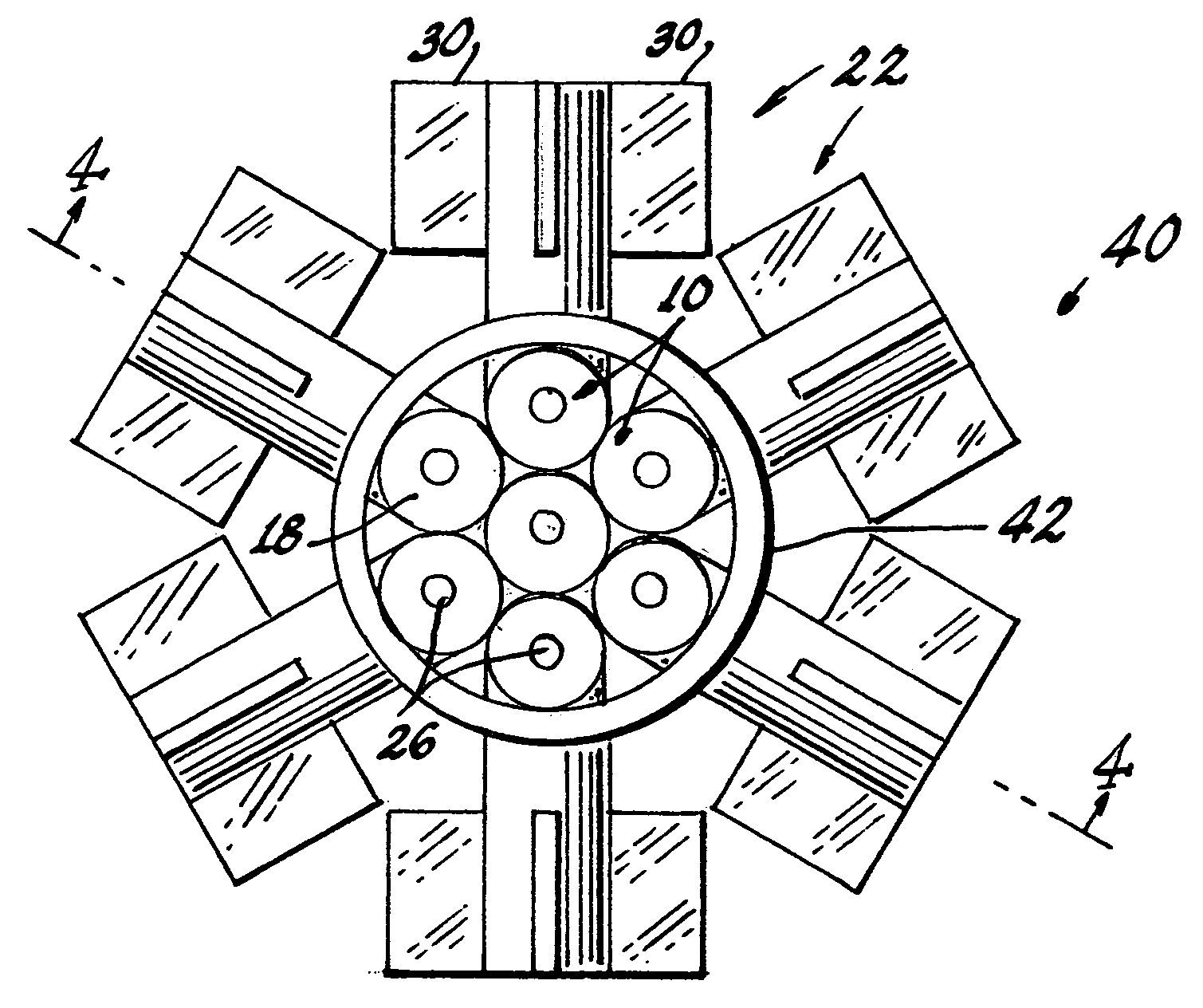
[0010]In another embodiment of the invention, a plurality of the light sources are combined to form a lamp, which, while useable in many applications, is efficiently used for down lighting.
[0011]The light sources are convenient, of small size and light weight, use readily available materials and are economical to manufacture.

Problems solved by technology

While LEDs now approach the performance level of traditional light sources, they require the heat-dissipaters to maintain their light output and expected life times. While this problem (heat removal) is not great when low-power LEDs (below 0.5 watts) are used, it becomes a serious problem in applications that call for high power density.
Such structures are relatively massive and difficult to fabricate.
Other, large scale heat pipes have also been proposed, for large scale cooling operations, for example, those shown in U.S. Pat. Nos. 2,350,348 and 3,229,759; however, these relatively massive devices are virtually incompatible with small scale LEDs and, moreover, do not provide for direct LED mounting.

Method used


Image

  • LED light source with an integrated heat pipe
  • LED light source with an integrated heat pipe
  • LED light source with an integrated heat pipe

Examples


Embodiment Construction

[0016]For a better understanding of the present invention, together with other and further objects, advantages and capabilities thereof, reference is made to the following disclosure and appended claims taken in conjunction with the above-described drawings.

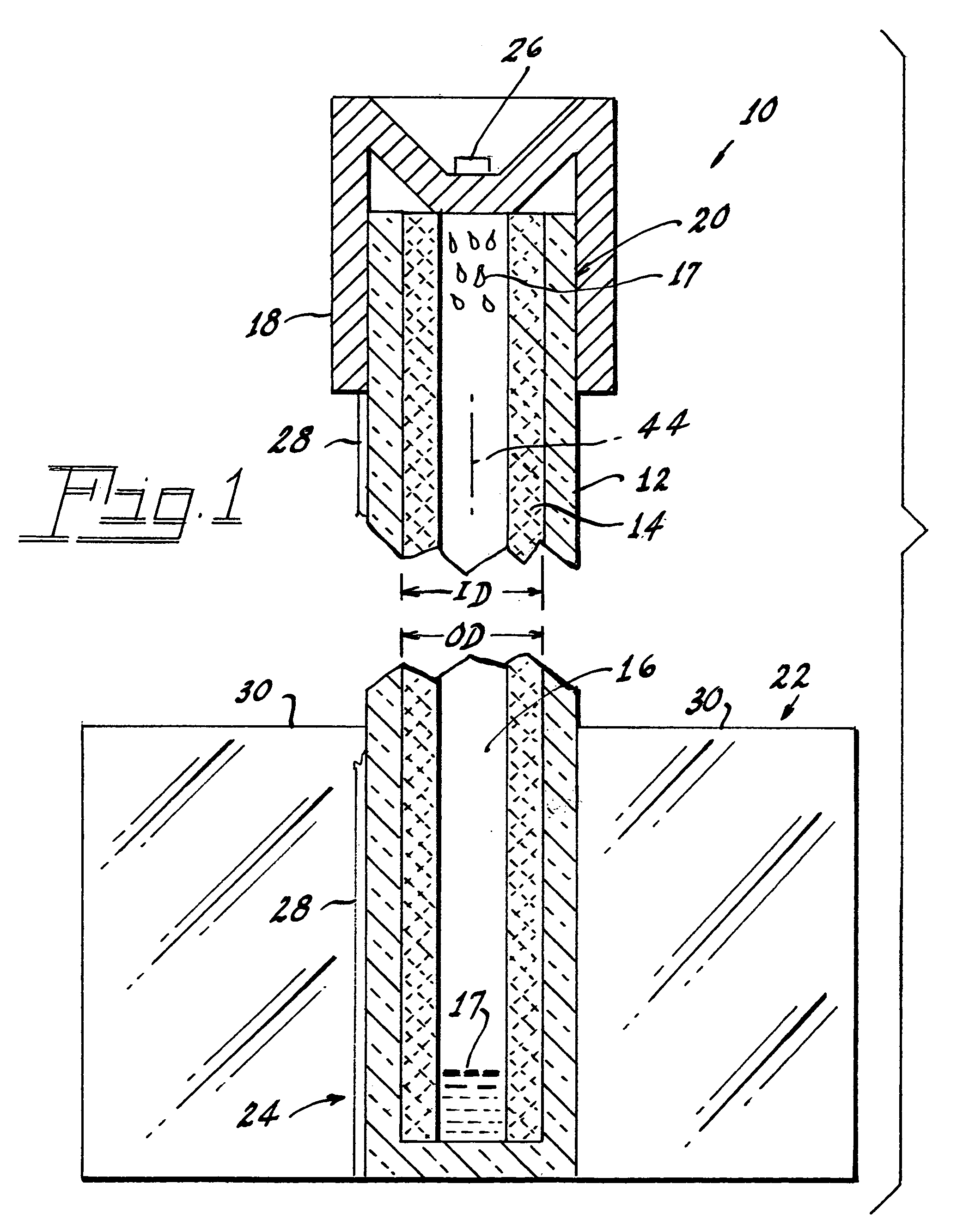
[0017]Referring now to the drawings with greater particularity, there is shown in FIG. 1 a light source 10 comprising a tubular glass heat pipe 12 having a given inside diameter ID. In a preferred embodiment, the glass sleeve 14 comprises lead glass tubing has an ID of 4 mm with a wall thickness of 0.5 mm and, therefore, an outside diameter of 5 mm.

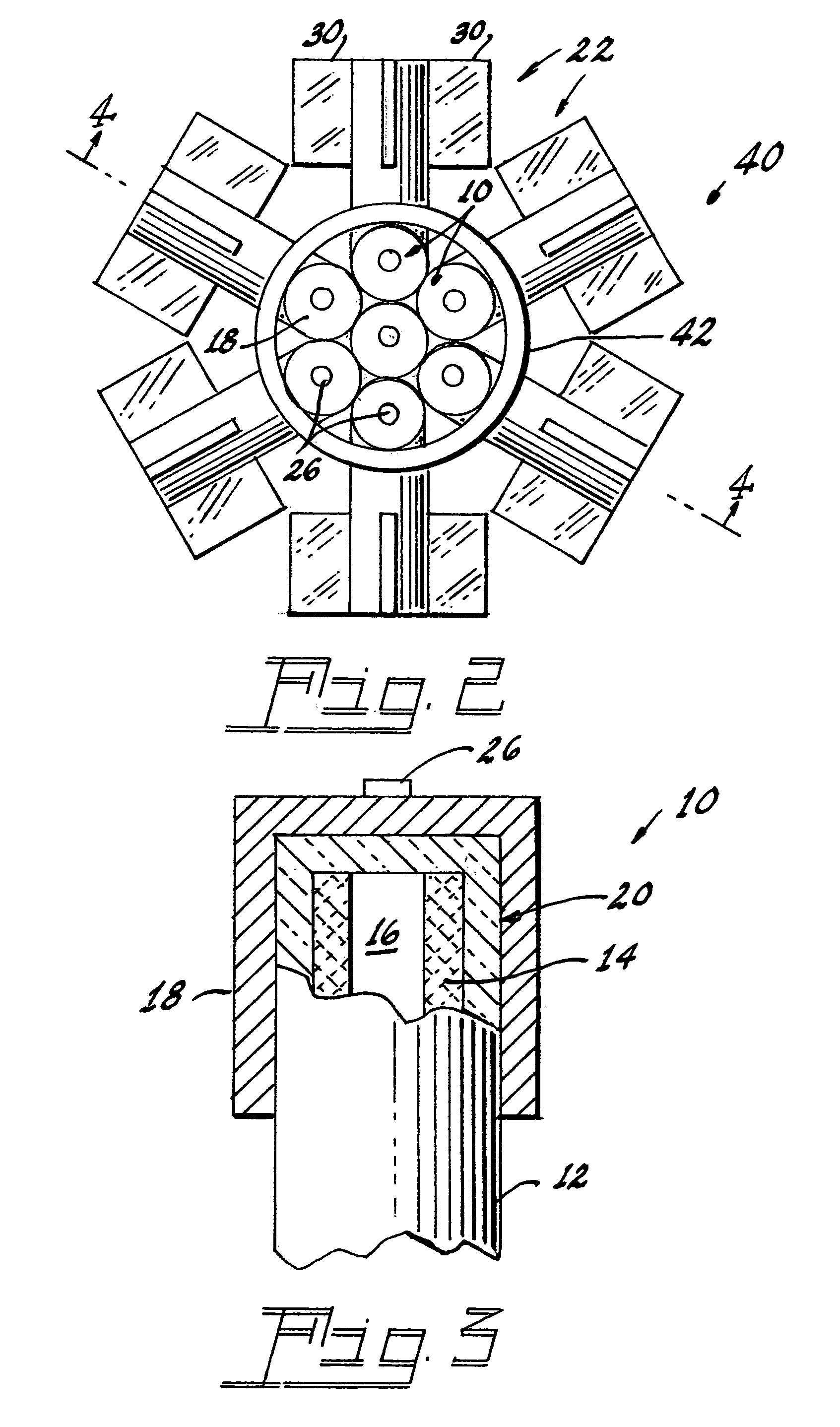
[0018]A metal cap 18 selected from the group of glass-sealing metals and alloys (such, for example, as Cartech 27) is fixed to a proximal end 20 of the glass heat pipe 12 by flame sealing.

[0019]A tubular fiberglass wick 14 is positioned within the glass heat pipe 12, the fiberglass wick 14 having an outside diameter OD substantially equal to the given inside diameter ID of the glass tu...


PUM


Abstract

A light source (10) comprises a tubular glass heat pipe (12) having a given inside diameter ID. A tubular fiberglass wick (14) is positioned within the glass heat pipe (12). The fiberglass wick (14) has an outside diameter OD substantially equal to the given inside diameter ID and has a substantially centrally located open chamber (16) extending the length thereof. A quantity of an evaporable-condensable medium (17) is provided within the glass heat pipe (12) and a metal cap (18) selected from the group of glass-sealing metals and alloys is fixed to a proximal end (20) of the glass heat pipe (12). Heat dissipaters (22) are fixed to the distal end (24) of the heat pipe (12) and a light emitting diode (26) is fixed to the metal cap (18). Power conducting traces (28) are formed with the heat pipe (12) and are electrically connected to the light emitting diode (26). A lamp (40) can be formed with a plurality of the light sources (10).

Description

TECHNICAL FIELD[0001]This invention relates to light sources and more particularly to light sources employing light emitting diodes (LED or LEDs). Still more particularly, it relates to lamps using LEDs as the light source and to cooling structures for use with such light sources.BACKGROUND ART[0002]LEDs as light sources for illumination have greatly improved, enabling applications for so-called general light purposes, as opposed to the prior use as warning lights, for example. While LEDs now approach the performance level of traditional light sources, they require the heat-dissipaters to maintain their light output and expected life times. While this problem (heat removal) is not great when low-power LEDs (below 0.5 watts) are used, it becomes a serious problem in applications that call for high power density.[0003]Typically, heat dissipation is dealt with by a variety of means, such, for example, as substantial heat sinks; forced convection, circulating cooling liquid; heat pipes;...

Claims


Application Information

Patent Timeline
Patent Type & Authority Applications(United States)
IPC IPC(8): F21V29/00F21V21/00
CPCF21S8/02F21S48/328F21Y2101/02F21V29/006F21V29/2212F21V29/004F21Y2115/10F21V29/70F21V29/74F21V29/51F21S45/47
Inventor JOHNSTON, DAVID W.ZASLAVSKY, GREGORYSERRE, JEFFREY J.
Owner OSRAM SYLVANIA INC
Learn More