Display device for vehicle

a technology for display devices and vehicles, applied in the direction of simultaneous indication of multiple variables, identification means, instruments, etc., can solve the problem that the fundamental objective of darkened images cannot be achieved, and achieve the effect of improving the visibility of images, reducing the luminance of images, and securing a certain amount of luminan

Active Publication Date: 2010-04-01
DENSO CORP +1
View PDF9 Cites 9 Cited by
  • Summary
  • Abstract
  • Description
  • Claims
  • Application Information

AI Technical Summary

Benefits of technology

[0006]A display device for vehicle among several display devices is used not only under a bright environment of an outside illumination but also under a dark environment of an outside illumination such as in a night time drive, in a dark place drive, etc. Therefore, in a dark environment of an outside illumination, it is possible to improve visibility of an image by reducing an image luminance on the LCD by changing a gradient level of the LCD while keeping a source luminance of a light source according to the above-mentioned patent documents 1. However, as of images for calling a vehicle occupant's attention, such as an outside image provided by capturing a vehicle outside that needs attention, or a warning image which warns of vehicle abnormalities that need attention, it is necessary to keep the fundamental objective of displaying such an image by securing a certain amount of luminance. Therefore, if the gradient level of the LCD is changed according to the above-mentioned patent documents 1, the image which shall be illuminated with a bright luminance is also darkly displayed. This may cause a problem that the darkened image can not perform the fundamental objective.
[0009]According to the invention, when the adjust value for adjusting the luminance of the display image on the LCD is in a range brighter than the reference value, the first mode is performed. Therefore, both the gradient ratios of the first pixel and the second pixel are kept at the maximum ratios, but the source luminance of the light source is varied according to the adjust value. As a result, it is possible to correctly adjust both the luminance of the specific image and the luminance of the regular image respectively displayed on the first pixel and the second pixel by the source luminance of the light source until the luminance corresponding to the reference value. On the other hand, when the adjust value is in a range darker than the reference value, the second mode is performed. The source luminance of the light source is kept at the minimum source luminance. Under this condition, the gradient ratio of the second pixel is varied according to the adjust value, and, but, the gradient ratio of the first pixel is kept at the maximum ratio. As a result, it is possible to keep and maintain the luminance of the specific image displayed on the first pixel at the luminance corresponding to the reference value by keeping and maintaining both the source luminance of the light source and the gradient ratio of the first pixel, simultaneously suppressing the luminance of the regular image displayed on the second pixel by varying the gradient ratio of the second pixel. As mentioned above, the device allows a user to adjust the luminance of the regular image which is displayed at both the regular time and the specific time to a luminance that can provide a good visibility suitable for a taste of a vehicle occupant. On the other hand, the device can secure the luminance necessary for achieving the fundamental objective of the specific image displayed at the specific time.
[0010]In a second aspect of the invention in claim, the reference value is an adjust value corresponding to a luminance that is at least necessary for displaying the specific image. According to the invention, even if the adjust value becomes in a range darker than the reference value, it is possible to securely achieve a displaying objective of the specific image at the specific time, since the luminance of the specific image can be securely kept at least at the luminance corresponding to the reference value, i.e., the luminance at least necessary for displaying the specific image. In addition, in a case where the adjust value is in a range brighter than the reference value, it is possible to decrease the luminance of the specific image to at least necessary minimum luminance. Therefore, it is possible to extend a variable range of the luminance of the specific image as wide as possible. Therefore, it is possible to improve an adaptability of the luminance to the vehicle occupant's taste.
[0011]In a third aspect of the invention in claim, the control device controls the source luminance of the light source to the minimum source luminance, when the adjust value is equal to the reference value in the first mode, and controls the gradient ratio of the second pixel to the maximum ratio when the adjust value is equal to the reference value in the second mode. According to the invention, when the adjust value is equal to the reference value in the first mode where the source luminance of the light source is controlled variable, the control device controls the source luminance of the light source to the minimum source luminance which is continuously provided during the adjust value is in a range darker than the reference value in the second mode. Therefore, no change is generated on the source luminance of the light source when switching the control modes. In addition, when the adjust value is equal to the reference value in the second mode where the gradient ratio of the second pixel is controlled variable, the control device controls the gradient ratio of the second pixel to the maximum ratio which is continuously provided during the adjust value is in a range brighter than the reference value in the first mode. Therefore, no change of the gradient ratio of the second pixel is generated when switching the control modes. In addition, regarding the gradient ratio of the first pixel which is kept at the maximum ratio in both the first and second modes, no change is generated when switching the control modes. As a result, the luminance of the specific image and the regular image respectively displayed on the first pixel and the second pixel can be smoothly adjusted by avoiding a sudden change of the luminance responsive to a switching of the modes of control at the reference value which functions as a boundary. Therefore, it is possible to avoid a situation where a vehicle occupant might get a feeling of wrongness.

Problems solved by technology

This may cause a problem that the darkened image can not perform the fundamental objective.

Method used


Image

  • Display device for vehicle
  • Display device for vehicle
  • Display device for vehicle

Examples


first embodiment

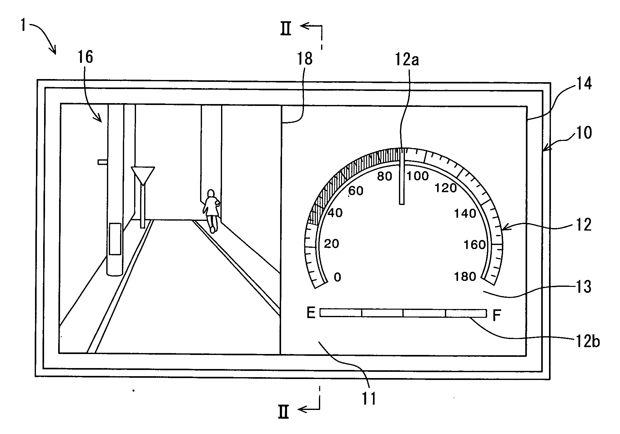
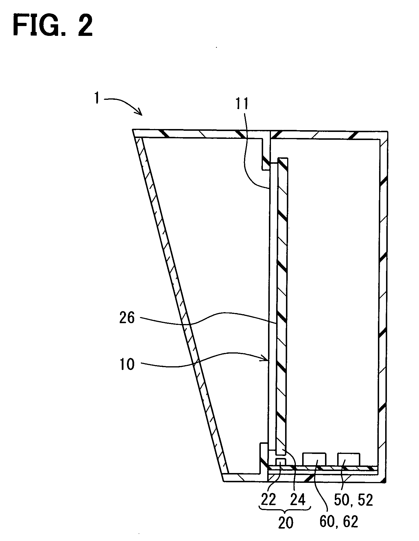
[0038]FIGS. 2 and 3 show schematic configuration of the vehicle display device 1 according to a first embodiment of the invention. FIG. 4 shows an electric circuit configuration of the device 1.

[0039]As shown in FIGS. 2-4, the vehicle display device 1 is a device for functioning as a combination meter. The device 1 comprises an LCD 10, a liquid crystal display, a light source 20, an input portion 30, an image capturing portion 40, an LCD driver portion 50, and a display controller portion 60, etc.

[0040]The LCD 10 is a TFT penetration LCD. The LCD 10 is installed in front of the driver's seat in a manner that a screen 11 faces to a driver's seat in the vehicle. The LCD 10 is a dot-matrix type which has a plurality of pixels arranged in a matrix form. The LCD 10 displays a full color image on the screen 11 by driving these pixels, respectively. In this embodiment, one pixel of the LCD 10 contains three-colored sub-pixels R, G and B which have a red, a green and a blue color filter res...

second embodiment

[0097]The second embodiment of the present invention is a modified embodiment of the first embodiment. In the following description, differences from the first embodiment are mainly described.

[0098]As shown in FIG. 11 and FIG. 12, an LCD 210 of a vehicle display device 200 in the second embodiment is provided with a second pixel region 218 that displays an warning image 216 and a background image 217 by driving the composing pixels and is located below the first pixel region 14. In FIG. 11, the two-dash line virtually shows a boundary between the first pixel region 14 and the second pixel region 218.

[0099]Here, the warning image 216 is an image which warns of an abnormality in order to call attention to the abnormality occurred on the vehicle. Therefore, the device displays the warning image 216 at the specific time at which an abnormality occurs as shown in FIG. 11, but, does not seemingly display the warning image 216 at the regular time as shown in FIG. 13. Especially in this emb...


PUM


Abstract

A display device for vehicle includes an LCD panel that has a first pixel region and a second pixel region. The display controller portion displays a meter image on the first pixel region at a regular time and a specific time, and displays an outside image on the second pixel region at the specific time. The display controller portion controls a gradient ratio of pixel in the first pixel region as a meter image gradient ratio, and controls a gradient ratio of pixel in the second pixel region as an outside image gradient ratio. The display controller portion switches and performs a first mode and a second mode. In the first mode, the display controller portion keeps both the meter image gradient ratio and the outside image gradient ratio to the maximum ratio R1max and R2max, and varies a source luminance of a light source according to an adjust value which is in a side brighter than a reference value Cb. In the second mode, the display controller portion keeps the source luminance of the light source at the minimum source luminance Lmin, varies the meter image gradient ratio according to an adjust value which is in a side darker than the reference value Cb, and keeps the outside image gradient ratio at the maximum ratio R2max. As a result, the multiple images in which the display objectives differ can be appropriately displayed to attain each objective.

Description

CROSS REFERENCE TO RELATED APPLICATION[0001]This application is based on Japanese Patent Application No. 2008-191406 filed on Jul. 24, 2008, the contents of which are incorporated herein by reference in its entirety.FIELD OF THE INVENTION[0002]The present invention relates to a vehicle display device including a liquid crystal display panel and a light source for the liquid crystal display panel.BACKGROUND OF THE INVENTION[0003]Conventionally, a display device for a vehicle etc. is known. The display device has a liquid crystal display panel for displaying an image, and a light source for illuminating the liquid crystal display panel. The liquid crystal display panel may be called as an LCD. It is also known that a gradient level of a pixel on the LCD and a source luminance of the light source are variable, and are adjusted in accordance with an adjust value for adjusting a brightness or luminance of a displayed image.[0004]For example, a display device disclosed in the patent docum...

Claims


Application Information

Patent Timeline
IPC IPC(8): G09G3/36G09F9/00
CPCB60K35/00G01D7/02G01D11/28G09G3/18G09G3/3406G09G2360/145G09G2320/0606G09G2320/0626G09G2320/0686G09G2360/144G09G3/3611
Inventor YOKOTA, NAOKISHIBATA, YUKIHIDEOKITA, MUNECHIKA
Owner DENSO CORP
Why Eureka
Try Eureka