
Portable wire spool holding device

a wire spool and holding device technology, applied in the direction of thin material handling, packaging, filament handling, etc., can solve the problems of hazardous wire spool sitting on the floor of a work site, cumbersome wire spools, unwieldy, etc., and achieve the effect of convenient use, convenient engagement, and quick, easy-to-reach wires

Inactive Publication Date: 2010-04-01
THOMPSON JERRY L
View PDF11 Cites 21 Cited by
  • Summary
  • Abstract
  • Description
  • Claims
  • Application Information

AI Technical Summary

Benefits of technology

[0013]It is, therefore, one of the primary objects of the present invention to provide a device for use in supporting a wire spool such that such wire spool is removed from the ground thereby eliminating the possibilities of worker's tripping on such wire spool.
[0014]Another object of the present invention is to provide a convenient to use device for supporting at least one wire spool between two vertical supports such as wooden studs.
[0015]Still another object of the present invention is to provide a device which includes a pair of support members for supporting a cross bar there between; such cross bar fitting through a center portion of a wire spool to support such spool and enable a user to un-spool wire there from quickly, easily, and efficiently.
[0016]Yet another object of the present invention is to provide a wire spool holding device releasably attachable to two supports, such as wooden studs, such wire spool holding device being portable and easy to engage with and release from such supports such that it can be used over and over again to the advantage of a user.
[0017]Still yet another object of the present invention is to provide a wire spool holding device releasably attachable to two supports, such as wooden studs, such wire spool holding device being portable and easy to engage with a range of different sized and shaped supports such that it can be used over and over again to the advantage of a user.

Problems solved by technology

Such wire spools are cumbersome, unwielding, and difficult to retrieve wire therefrom.
Additionally, having a wire spool sitting on the floor of a work site can be hazardous as construction workers, electricians, carpenters, and other workers may trip over such wire spool injuring themselves or damaging the work site.

Method used


Image

  • Portable wire spool holding device
  • Portable wire spool holding device
  • Portable wire spool holding device

Examples


Embodiment Construction

, particularly, when such description is taken in conjunction with the attached drawing figures and with the appended claims.

BRIEF DESCRIPTION OF THE DRAWINGS

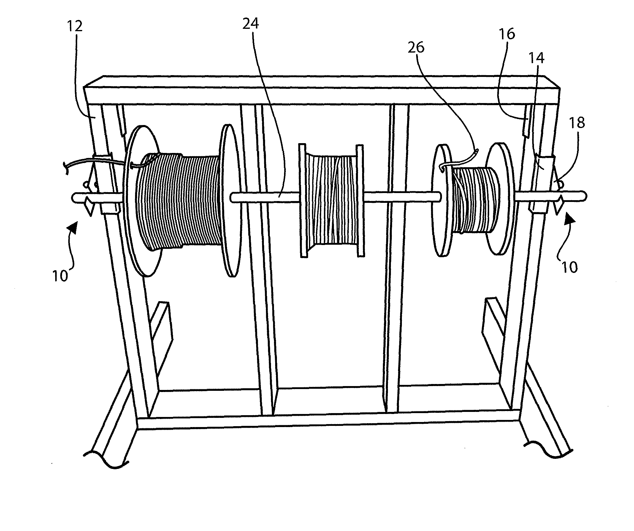
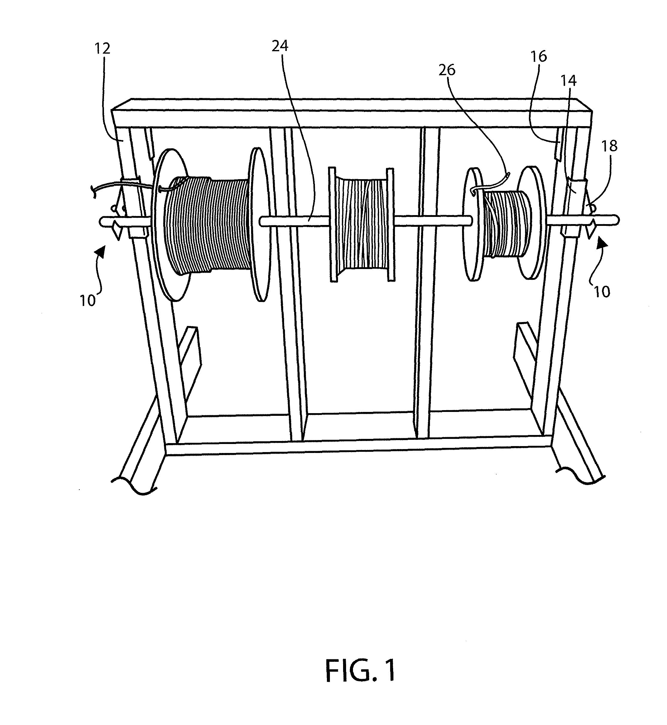
[0019]FIG. 1 is a front perspective view of the present invention in use with supported spools.

[0020]FIG. 2 is a general perspective view of the components of the present invention.

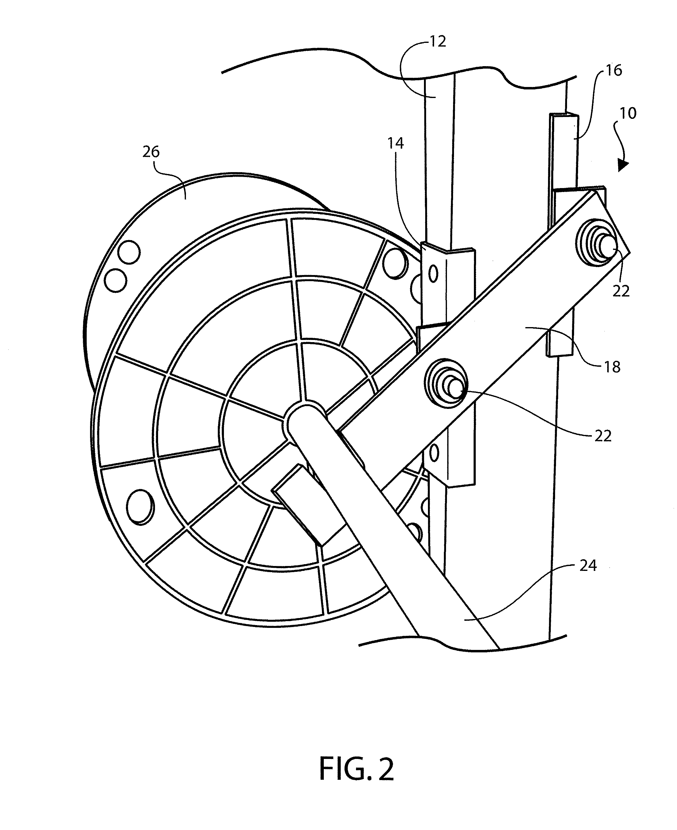
[0021]FIG. 3 is a close up view of the present invention gripping a vertical support.

BRIEF DESCRIPTION OF A PRESENTLY PREFERRED AND VARIOUS ALTERNATIVE EMBODIMENTS OF THE INVENTION

[0022]Prior to proceeding to the more detailed description of the present invention it should be noted that, for the sake of clarity and understanding, identical components which have identical functions have been identified with identical reference numerals throughout the several views illustrated in the drawing figures.

[0023]Reference is now made, more particularly, to FIGS. 1-3 which show a preferred embodiment of the present invention. Each support member 10 is designed...


PUM


Abstract

The present invention provides a spool holding device. The spool holding device in several embodiments includes at least two separate mechanical devices for supporting a cross bar between to vertical supports. Each mechanical device can be comprised of three primary components, two gripping elements connected by a leveraged bar support element. The leveraged bar support element can be adapted to hold a cross bar member. In several embodiments the levered bar support element has a notch for holding a cross member on one end, is connected to a gripping element on the other end and a second gripping element connected between the notch and the other gripping element. Both gripping elements are connected to leveraged bar support element in a way that allows for at least partial free rotation of each element, for example a bolt, washer and nut arrangement could be used.

Description

CROSS REFERENCE TO RELATED APPLICATION[0001]This patent application is related to and claims priority from U.S. Provisional Patent Application Ser. No. 61 / 194,425 filed Sep. 26, 2008.FIELD OF THE INVENTION[0002]The present invention relates, in general, to wire spool holding devices and, more particularly, this invention relates to a wire spool holding device which can be attached to two wooden studs.BACKGROUND OF THE INVENTION[0003]Prior to the conception and development of the present invention, wire spools, as are generally well known in the prior art, are used to hold various types of electrical wire. Such wire spools are cumbersome, unwielding, and difficult to retrieve wire therefrom. Additionally, having a wire spool sitting on the floor of a work site can be hazardous as construction workers, electricians, carpenters, and other workers may trip over such wire spool injuring themselves or damaging the work site.[0004]Specifically of interest to the present invention are the f...

Claims


Application Information

Patent Timeline
Patent Type & Authority Applications(United States)
IPC IPC(8): B65H49/32B65H49/20B65H49/26
CPCB65H49/32B65H49/327B65H49/325
Inventor THOMPSON, JERRY L.
Owner THOMPSON JERRY L
Learn More