
Thermochemical reactor for a self-propelled harvesting vehicle

Inactive Publication Date: 2010-04-01
CLAAS SELBSTFAHRENDE ERNTEMASCHINEN GMBH
View PDF5 Cites 7 Cited by
  • Summary
  • Abstract
  • Description
  • Claims
  • Application Information

AI Technical Summary

Benefits of technology

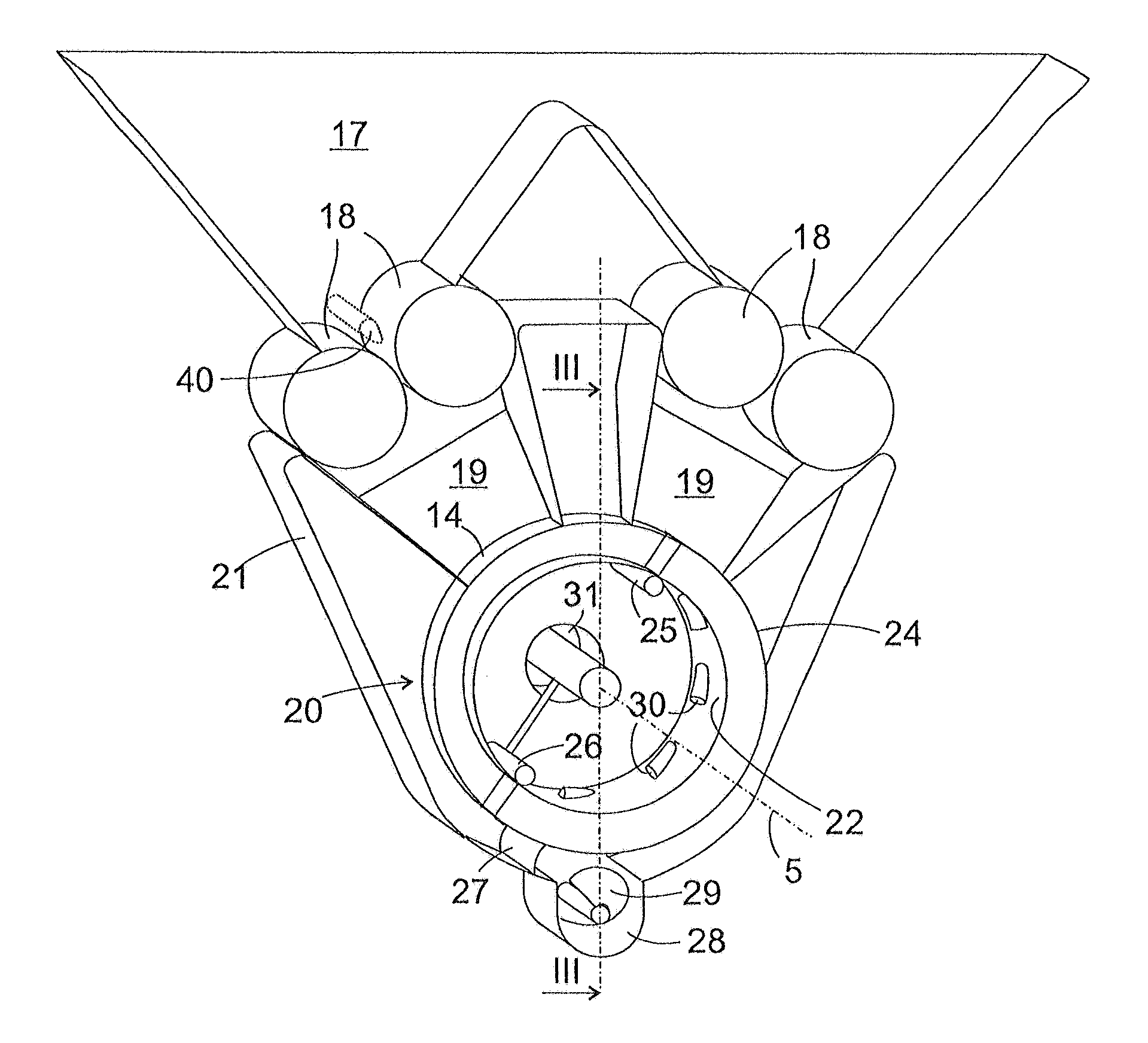
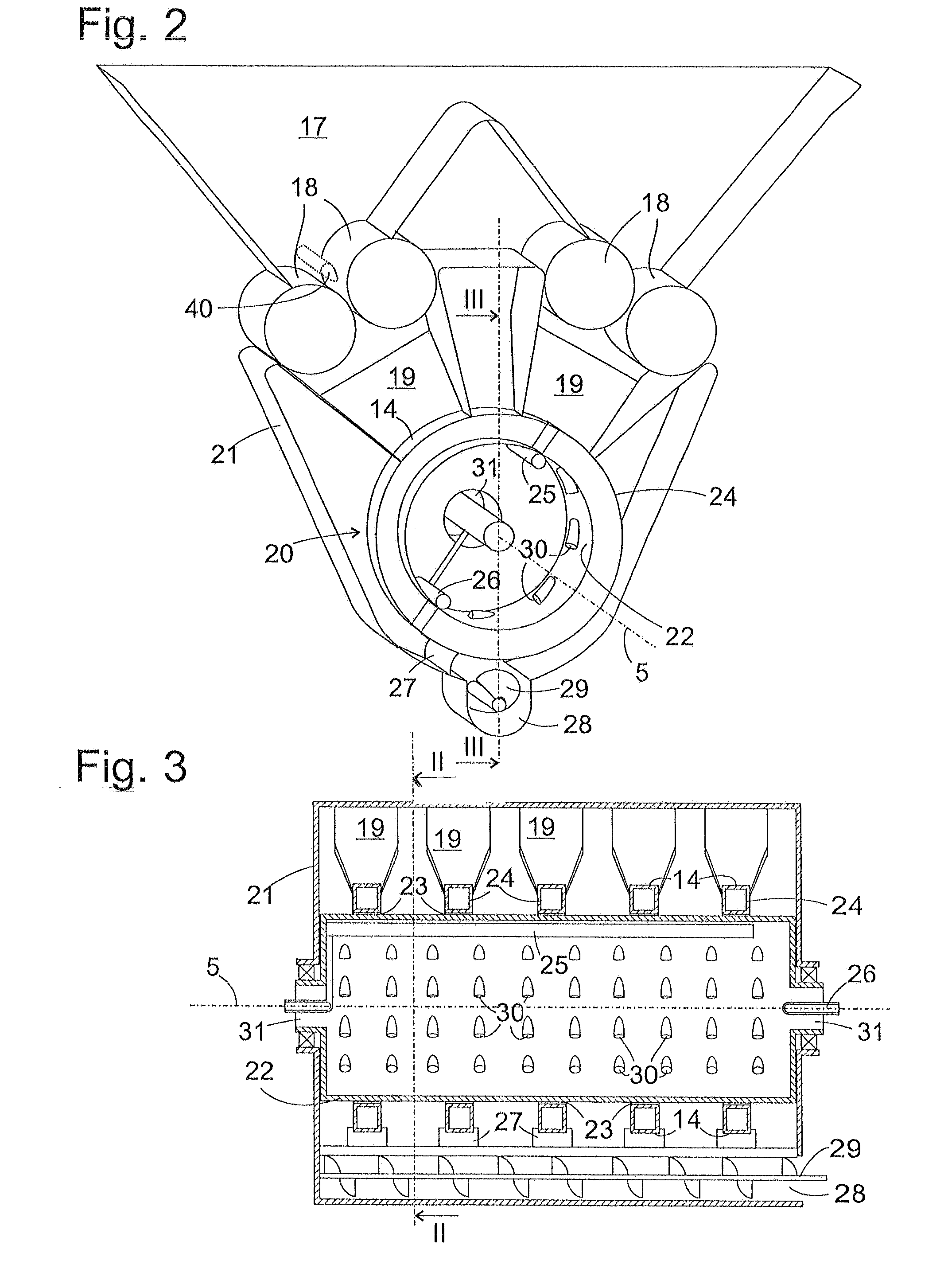
[0007]One object of the present invention, therefore, is to create a thermochemical reactor for ablative flash pyrolysis which attains uniform reaction conditions on the entire contact surface between the raw material and the contact body, and makes good use of the available surface of the contact body.
[0008]The object is attained by the fact that, in the case of a thermochemical reactor which includes a reaction body that is rotatable about an axis and on which the pyrolysis reactions take place, and which includes a pressing device for pressing raw material to be pyrolyzed against a contact surface of the reaction body, the contact surface represents at least a portion of a circumferential surface of the reaction body. Due to this design, the variability of the relative speed between the contact surface and the raw material is reduced across the cross section of the contact between the two, as compared to the known contact disk. It is therefore possible to provide a large contact surface having homogeneous reaction conditions in one compact design.

Problems solved by technology

One problem that is associated with the use of biomass as an energy source is its water content which is usually high.
Fresh vegetable biomass generally has a water content that is so high that the attainable yield of fuel does not cover the costs and energy required to harvest and haul the biomass to a stationary pyrolysis unit.
The problem results that it is difficult to ensure an even temperature distribution on the disk which is heated by the burner, on its side facing away from the raw material, and that the speed at which the disk and raw material move relative to one another depends on the distance between the contact point and the rotational axis of the disk.
The greater this portion is, the greater the radius range is across which the contact surface extends, and the more non-uniform the conditions are under which the conversion takes place, thereby making it that much more difficult to control the process.

Method used


Image

  • Thermochemical reactor for a self-propelled harvesting vehicle
  • Thermochemical reactor for a self-propelled harvesting vehicle
  • Thermochemical reactor for a self-propelled harvesting vehicle

Examples


second embodiment

[0050] shown in FIG. 4, in a step that is analogous to FIG. 3, support cylinder 22 includes large surface-area openings between heat exchanger rings 24, which are filled with a filter, e.g., plates 32 of a porous ceramic material. The size of plates 32 depends on the requirements on the mechanical loading capacity of drum 20; in a borderline case, the jacket surface of reactor drum 20 may be composed entirely of the ceramic material, even in the regions enclosed by heat exchanger rings 24.

[0051]In this second embodiment, the solid particles that are contained in the pyrolysis gas that is released on outer surfaces 14 of heat exchanger rings 24 are separated out on the outside, on filter plates 32, and, analogous to doctor blades 27 that clean outer surfaces 14, doctor blades or brushes 33 may be provided in order to scrape the particles off of plates 32 near the bottom of reactor housing 21. The coke particles that are scraped or brushed off of filter plates 32 are then removed from...

third embodiment

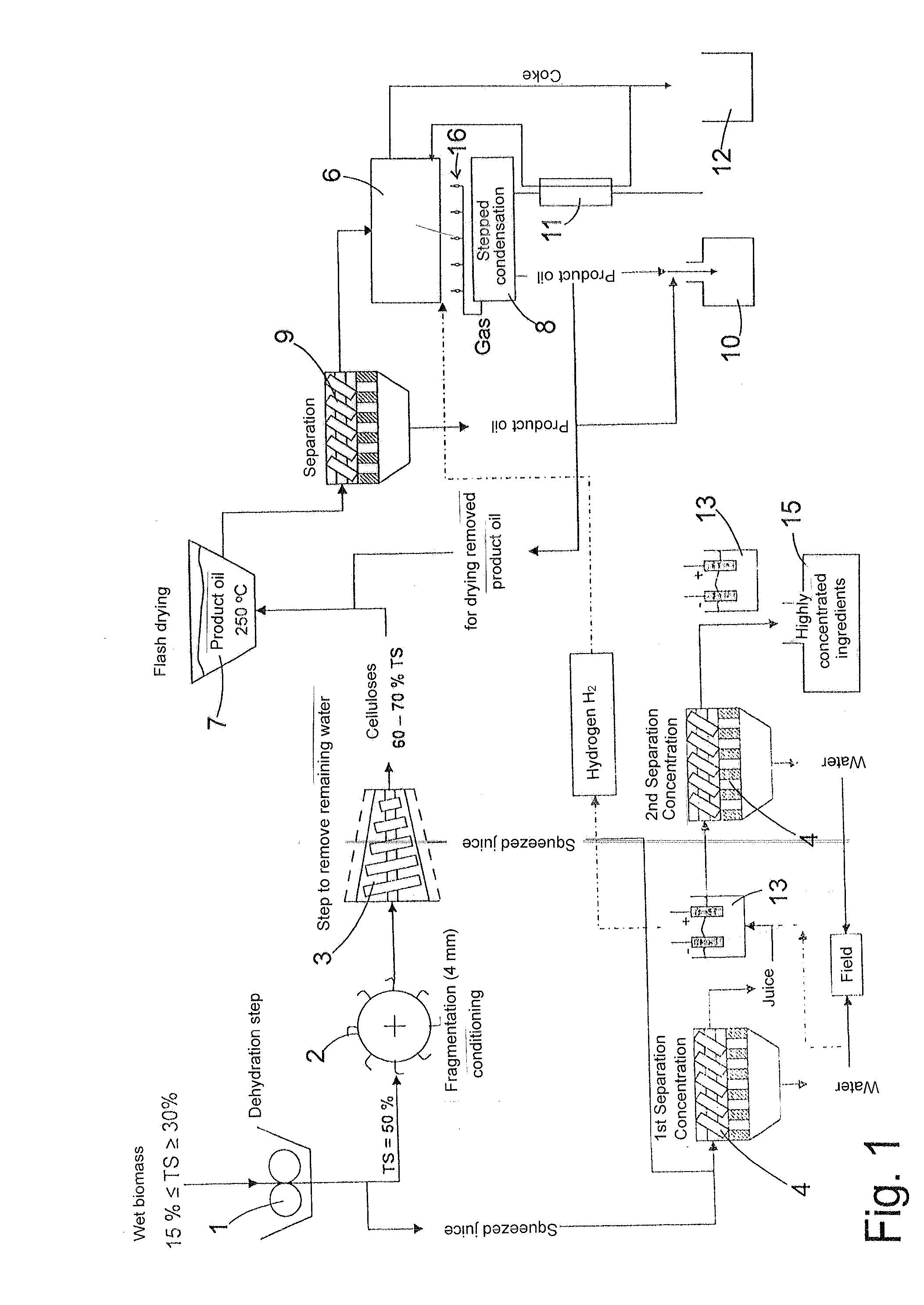
[0052]FIG. 5 shows a partial cross section through a reactor according to the present invention. A plurality of the components shown in FIG. 1 is integrated in this design. For example, a flat, open shell 34 located in the upper region of the figure functions simultaneously as drying step 7 and a hopper which corresponds to hopper 17 in FIG. 2, and which is used to supply reactor 6. A plurality of augers 35 which mix the biomass with hot product oil that is added extends in shell 34, in alternating directions and transversely to the cutting plane.

[0053]Additional conveyor augers 36 having a substantially vertical axis extend into downwardly oriented channels 37 which emerge from the bottom of shell 34 in order to press the biomass to which product oil was added into channels 37 and compact it there. The wall of channels 37 includes a sieve-like structure in a section 38 through which excess product oil from the mass may exit and flow to tank 10. A downstream section 39 of channels 3...


PUM

PropertyMeasurementUnit
Angleaaaaaaaaaa
Radiusaaaaaaaaaa

Abstract

A thermochemical reactor includes a contact surface and a pressing device for pressing raw material to be pyrolyzed against the rotationally symmetrical contact surface which is rotatable relative to the raw material. A generating line of the contact surface is oriented at an angle to a radius that is perpendicular to the axis of the relative rotation.

Description

CROSS-REFERENCE TO A RELATED APPLICATION[0001]The invention described in claimed herein below is also described in German patent application DE 10 2008 049 350.3 filed on Sep. 29, 2008. This German patent application, whose subject matter is incorporated here by reference, provides the basis for a claim of priority of invention under 35 U.S.C. 119 (a-d).BACKGROUND OF THE INVENTION[0002]The present invention relates to a thermochemical reactor for extracting gaseous or liquid fuel from a raw material, preferably from biomass, via pyrolytic conversion.[0003]In the light of a forseeable shortage of fossil fuels and the effects of their use on the climate, the public interest in the utilization of sustainable raw materials, i.e., biomass, as an energy source is increasing. One problem that is associated with the use of biomass as an energy source is its water content which is usually high. Fresh vegetable biomass generally has a water content that is so high that the attainable yield of...

Claims


Application Information

Patent Timeline
IPC IPC(8): A01D43/06B01J8/00
CPCC10B47/12C10B47/14C10B53/02Y02E50/32C10C5/00Y02E50/14C10B57/12Y02E50/10Y02E50/30
Inventor WEIGELT, HORST
Owner CLAAS SELBSTFAHRENDE ERNTEMASCHINEN GMBH
Learn More