
Method of initializing bolt pretension in a finite element analysis

a finite element analysis and pretension technology, applied in the field of methods, can solve the problems of many prior art approaches that are cumbersome and/or tedious for users not, inaccurate pretension of many bolts, and the inability to accurately simulate bolted joints, etc., and achieve the effect of small increments

Active Publication Date: 2010-03-25
ANSYS
View PDF2 Cites 20 Cited by
  • Summary
  • Abstract
  • Description
  • Claims
  • Application Information

AI Technical Summary

Benefits of technology

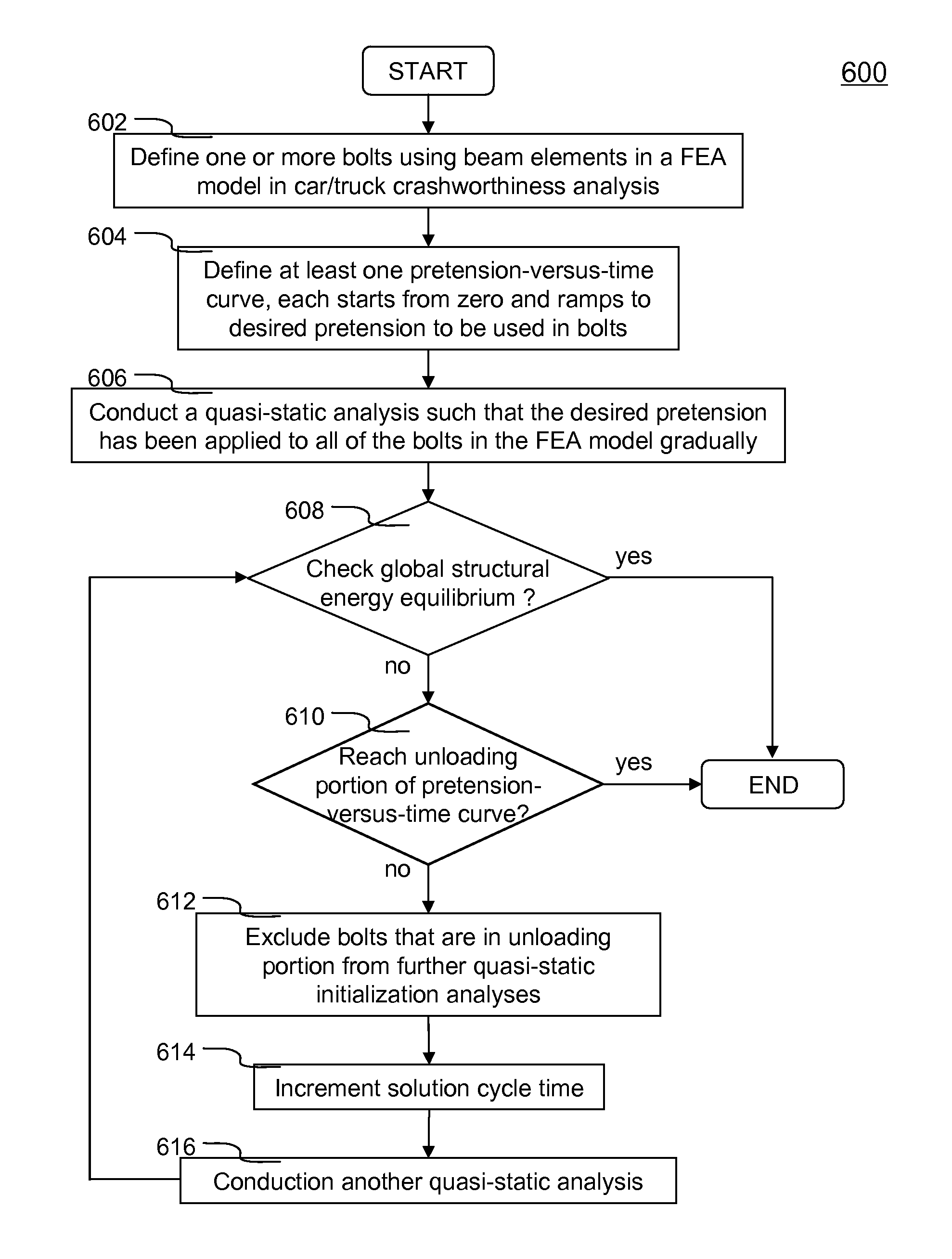
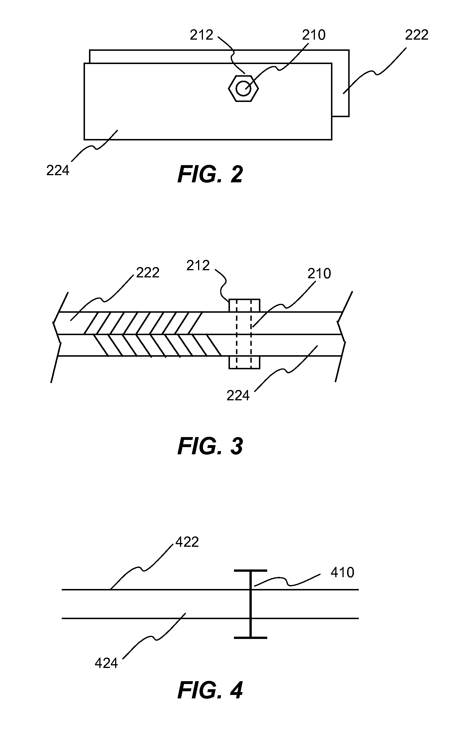
[0008]The present invention discloses a system, method and software product for numerically initializing bolt pretension independent of the axial strain in a finite element analysis. Pretension of a bolt in a bolted joint or connection is determined from physical data (e.g., torque of the wrench used for tightening the bolt). When there are more than one bolt in a structure (e.g., car, truck, etc.), each bolt may have a different pretension and may be situated in a different orientation. In one aspect of the present invention, each bolt is modeled using a beam element in a finite element analysis model. Each beam element includes two end nodes which correspond to the two ends of the bolt. To apply the desired pretension to one or more bolts, at least one pretension-versus-time curve is specified. Each pretension-versus-time curve includes a ramp portion, a desired pretension portion and an optional unloading portion. Duration of the pretension-versus-time curve generally covers first 0.5-1% of total simulation time (about 100 ms or 0.1 second) of a car crashworthiness analysis. Ramp portion starts from zero to the desired pretension in a substantially linear manner, and hence being configured for applying desired pretension to a bolt gradually with substantially smaller increments. Desired pretension portion is configured for ensuring the desired pretension can actually be applied to the beam element during an initialization process—a series of quasi-static analyses. Because the desired pretension in bolts can be imposed independent of the deformation of the beam or independent of axial strain, the method according to one aspect of the present invention overcomes the problems encountered in prior art approaches. In particular, the method of the present invention completely avoids the need to iteratively determine an axial strain or displacement used for deriving the desired pretension. Unloading portion is configured for signaling that desired pretension has been reached and applied to the bolt.

Problems solved by technology

A problem associated with crashworthiness simulation is to properly simulate bolted joints or connections between two parts especially in trucks.
Many prior art approaches are cumbersome and / or tedious for users not only in creation of the FEA model, but in actual simulation itself.
Since typical FEA models may contain hundreds of bolts in close proximity, the interactions that result leave many bolts with inaccurate pretensions.
The primary reason for bolt pretension not reaching the desired level is due to deformation of the plates or other components within the bolted joints.

Method used


Image

  • Method of initializing bolt pretension in a finite element analysis
  • Method of initializing bolt pretension in a finite element analysis
  • Method of initializing bolt pretension in a finite element analysis

Examples


Embodiment Construction

[0021]In the following description, numerous specific details are set forth in order to provide a thorough understanding of the present invention. However, it will become obvious to those skilled in the art that the present invention may be practiced without these specific details. The descriptions and representations herein are the common means used by those experienced or skilled in the art to most effectively convey the substance of their work to others skilled in the art. In other instances, well-known methods, procedures, components, and circuitry have not been described in detail to avoid unnecessarily obscuring aspects of the present invention.

[0022]Reference herein to “one embodiment” or “an embodiment” means that a particular feature, structure, or characteristic described in connection with the embodiment can be included in at least one embodiment of the invention. The appearances of the phrase “in one embodiment” in various places in the specification are not necessarily ...


PUM


Abstract

In one aspect of the invention, each bolt is modeled using a beam element in a FEA model. To apply desired pretension to one or more bolts, at least one pretension-versus-time curve is specified. Each pretension-versus-time curve includes ramp portion, desired pretension portion and optional unloading portion. Duration_of the pretension-versus-time curve generally covers first 0.5-1% of total simulation time of a car crashworthiness analysis. Ramp portion starts from zero to desired pretension in a substantially linear manner, and hence being configured for applying desired pretension to a bolt gradually with smaller increments. Desired pretension portion is configured for ensuring the desired pretension can actually be applied to the beam element during an initialization process—a series of quasi-static analyses. Since the method is independent of the deformation of the beam, the method completely avoids the need to iteratively determine an axial strain or displacement that gives the desired pretension.

Description

FIELD OF THE INVENTION[0001]The present invention generally relates to a method, system and software product used in computer-aided engineering analysis, more particularly to a method of initializing bolt pretension independent of the axial strain in a finite element analysis for simulating structural responses of a structure with bolted joints included therein.BACKGROUND OF THE INVENTION[0002]Finite element analysis (FEA) is a computer implemented method widely used in industry to model and solve engineering problems relating to complex systems such as three-dimensional non-linear structural design and analysis. FEA derives its name from the manner in which the geometry of the object under consideration is specified. With the advent of the modern digital computer, FEA has been implemented as FEA software. Basically, the FEA software is provided with a model of the geometric description and the associated material properties at each point within the model. In this model, the geometr...

Claims


Application Information

Patent Timeline
Patent Type & Authority Applications(United States)
IPC IPC(8): G06G7/70G06G7/48
CPCG06F17/5018G06F30/23
Inventor HALLQUIST, JOHN O.
Owner ANSYS
Learn More