
Interference-Rejection Coding Method For An Optical Wireless Communication System And The Optical Wireless Communication System Thereof

a technology of optical wireless communication and coding method, applied in electromagnetic transmission, electrical equipment, transmission, etc., can solve the problems of affecting the use of other electronic instruments, affecting the safety of communication, so as to reduce the demands on the specification and the cost of analog front-end, and effectively and stably reject optical interference

Inactive Publication Date: 2010-03-25
CHEN YUAN +2
View PDF59 Cites 8 Cited by
  • Summary
  • Abstract
  • Description
  • Claims
  • Application Information

AI Technical Summary

Benefits of technology

"The present invention provides an interference-rejection coding method for optical wireless communication systems. It uses delay modulation and block code to modulate data signals and a narrow-band band-pass filter to reject optical interference. The transmitting and receiving ends have corresponding modulation and demodulation structures for correct demodulation of the signals. The interference-rejection coding scheme can be used in various applications such as optical WLAN, data transmission of medical facilities, wireless communication in the aircraft, and encrypted data transmission network. It also reduces the demands on the specification and the cost of analog front-end and can be used in low-priced transmission interfaces."

Problems solved by technology

However, the electromagnetic wave (EM wave) emitted from the wireless communication is potentially harmful to the health, and can also interfere with other electronic instruments.
Therefore, its use is usually restricted in the environment where sensitive electronic devices are widely used, such as in a hospital or an aircraft.
In addition, because wireless electronic networks are susceptible to eavesdropping or interception, they are unsuitable for applications such as military, government or financial institutes where data security is highly regarded.
This, however, may lead to the distortion of the signals, and generating the additional inter-symbol interference (ISI) effect.
But the conventional methods can only provide 0.2 dB of improvement in filtering the interference of fluorescent light.
The unfiltered fluorescent interference still creates a loss of 17 dB or more, and is unable to reject the interference entirely.
However, these techniques require additional modulation and demodulation mechanisms, and the system complexity is increased.
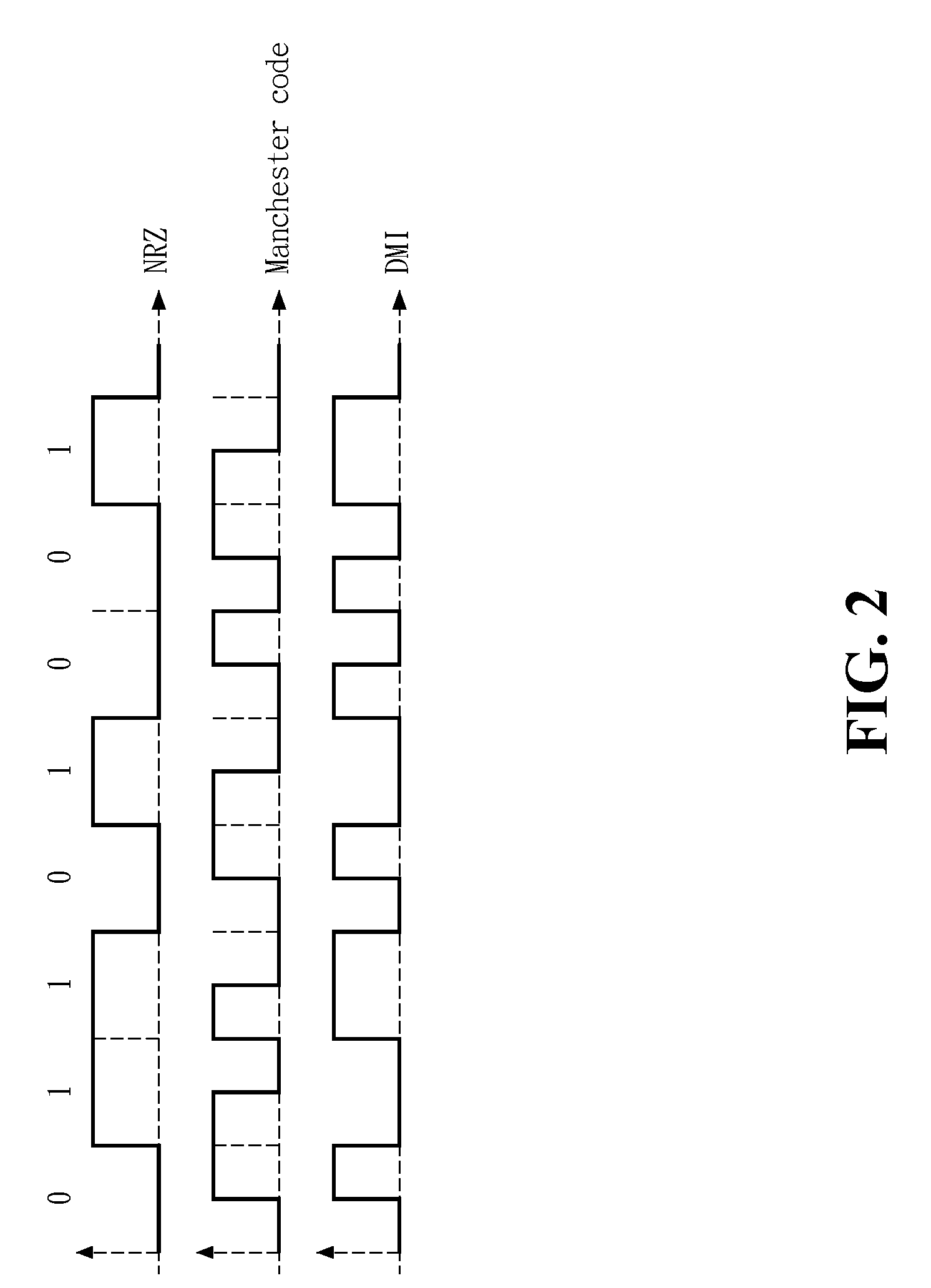
Although these techniques are simple, the disadvantages include the bandwidth requirement twice of that of conventional non return to zero (NRZ), the increasing received optical noise, transmission distortion, and higher demands on the optical components. FIG. 2 shows a waveform view of various line coding techniques, including NRZ, Manchester, DMI and delay modulation.
These techniques greatly increase the system complexity, transmission bandwidth requirement and impose higher demands on optical components.
The disadvantages of these techniques include the complexity of front-end circuitry and the uncertainty of interference improvement dependent on interference characteristics.
These techniques can improve the change of the signal bias, but are less effective for optical interference and these techniques increase the front-end circuitry complexity.
This, combined with the high propagation attenuation (20-40 dB) of the air, greatly limits the power of the signals received at the receiving end.
In addition, the indoor light sources, such as sun rays, fluorescent light, lamps, infra-red remote controllers, all contribute to the optical interference in the optical wireless communication.

Method used


Image

  • Interference-Rejection Coding Method For An Optical Wireless Communication System And The Optical Wireless Communication System Thereof
  • Interference-Rejection Coding Method For An Optical Wireless Communication System And The Optical Wireless Communication System Thereof
  • Interference-Rejection Coding Method For An Optical Wireless Communication System And The Optical Wireless Communication System Thereof

Examples


Embodiment Construction

[0024]The present invention uses the delay modulation together with block code to modulate the signal to high frequency, and then uses a narrow-band band-pass filter to reject the low-pass interference. FIG. 3 shows the signal frequency spectrum characteristics of various line coding schemes and the present invention. As shown in FIG. 3, the required bandwidth for the signal using delay modulation with block code of the present invention is less than that of other line coding techniques, such as Manchester or NRZ. This invention includes cascade coding and filtering and is applicable to wireless, medical or encrypted communication systems or environments.

[0025]At the transmitting end and the receiving end, the present invention arranges a pair of corresponding modulation and demodulation modules, respectively. Thereby, the receiving end may correctly decode the signals coded by the transmitted end. The present invention also uses delay modulation to concentrate the power of the opti...


PUM


Abstract

An interference-rejection coding method for an optical wireless communication system and such an optical wireless communication system are provided. The coding method uses delay modulation, block code techniques and filtering to reduce the low frequency interference from light sources. A plurality of codewords from the block codes are reserved for performing digital data recovery. The invention removes the need of analog clock data recovery circuit, and does not require complex hardware for realization. Therefore, it can be applied to a wide range of applications, such as optical WLAN, data transmission of medical facilities, wireless communication in the aircraft, encrypted data transmission network, and low-priced transmission interfaces.

Description

CROSS REFERENCE[0001]This is a continuation application of U.S. patent application Ser. No. 11 / 146,546, filed Jun. 7, 2005, which is incorporated herewith by reference.FIELD OF THE INVENTION[0002]The present invention generally relates to a coding scheme for optical wireless communication systems, and more specifically to an interference-rejection coding method for an optical wireless communication system and the optical wireless communication system thereof.BACKGROUND OF THE INVENTION[0003]As the wireless local area network (WLAN) becomes ubiquitous, the users of portable devices can easily find access points to surf the internet and obtain the information without the restriction imposed by the conventional wiring cables. However, the electromagnetic wave (EM wave) emitted from the wireless communication is potentially harmful to the health, and can also interfere with other electronic instruments. Therefore, its use is usually restricted in the environment where sensitive electron...

Claims


Application Information

Patent Timeline
Patent Type & Authority Applications(United States)
IPC IPC(8): H04B10/00
CPCH04B10/11
Inventor CHEN, YUANTSAI, SHANG-FENGHUNG, YUNG-HUA
Owner CHEN YUAN
Learn More