
Cardiac function display apparatus and program therefor

Active Publication Date: 2010-03-25
FUJIFILM CORP
View PDF7 Cites 25 Cited by
  • Summary
  • Abstract
  • Description
  • Claims
  • Application Information

AI Technical Summary

Benefits of technology

[0024]According to the present invention, a functional image representing a function of a heart in each position and a morphological image depicting morphology of a blood vessel are displayed in a superimposing manner such the each position of the heart in the functional image corresponds to each position of the heart in the morphological image, thereby allowing an observation of the heart by relating each function to the anatomical position.
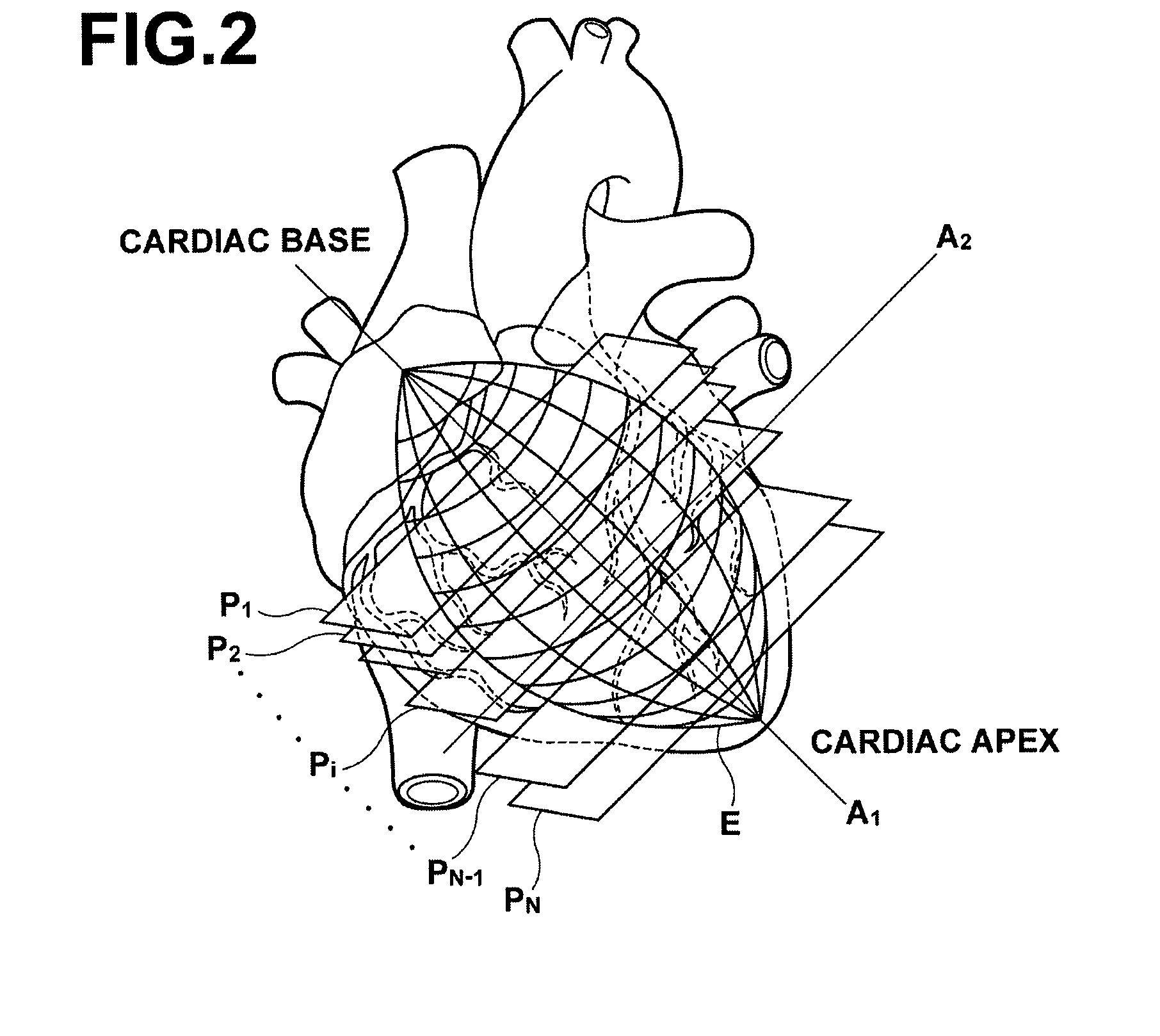
[0025]Further, images representing functions of the heart at a plurality of slice planes cut in a direction traversing a major axis extending from the cardiac base toward the cardiac apex of the heart are arranged concentrically, and an image of a slice plane near the cardiac base is disposed near the center of the concentrically arranged images and an image representing a function of a slice plane closer to the cardiac apex of the heart is disposed at a position farther away from the center, whereby a coronary artery of the morphological image displayed in a superimposing manner branches from the center toward the outside, so that an image allowing easy understanding of the anatomical position of the heart may be generated.
[0026]Further, generation of a morphological image by performing MIP processing (maximum intensity projection) on voxel data present within a predetermined distance from an outer myocardial wall of the heart which includes a blood vessel along the outer myocardial wall allows an image representing detailed morphology of the blood vessel to be generated and the anatomical position of the heart becomes more understandable.
[0027]Still further, the wider range of the blood vessel on the heart depicted in the morphological image than the range of the functions of the heart represented by the functional image may provide a portion in which the anatomical position of the hear can be confirmed without being restricted by the display area of the functional image when the morphological image and functional image are displayed in a superimposing manner, thereby facilitating understanding of the correspondence between the position and function of the heart.

Problems solved by technology

When a narrowed section of a blood vessel is discovered by the angiography system, however, it has not been possible to confirm with the functional image to what extent it has an adverse effect, because the position of the blood vessel and the position of the functional image are not matched.
Otherwise, it has not been possible to understand that an abnormal section appearing on the functional image corresponds to which part of the blood vessel.
The method described in Japanese Unexamined Patent Publication No. 2005-27999 in which a line is written on a bull's eye functional image by performing a coordinate transformation on the pass of a coronary artery, however, does not represent the morphology of the blood vessel actually running around the heart, so that it is difficult to determine which part of the coronary artery is observed.

Method used


Image

  • Cardiac function display apparatus and program therefor
  • Cardiac function display apparatus and program therefor
  • Cardiac function display apparatus and program therefor

Examples


Embodiment Construction

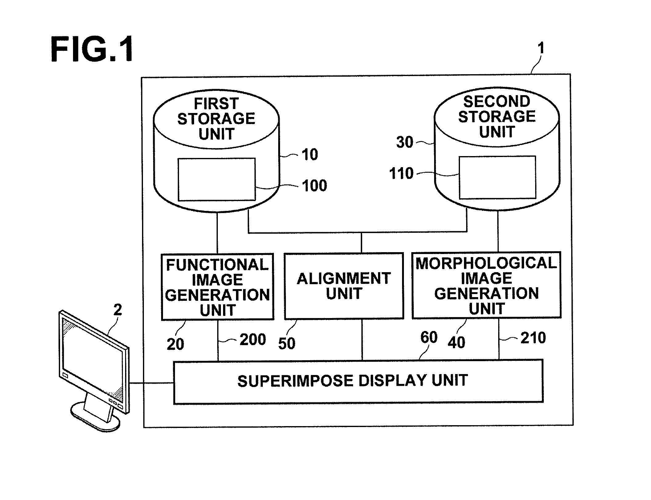
[0046]Hereinafter, an embodiment of the cardiac function display apparatus of the present invention will be described in detail with reference to the accompanying drawings. FIG. 1 is a schematic configuration diagram of the cardiac function display apparatus of the present invention. The configuration of cardiac function display apparatus 1 shown in FIG. 1 is realized by executing a cardiac function display processing program, read in an auxiliary storage device, on a computer. Here, the cardiac function display processing program is stored in recording medium, such as a CD-ROM or the like, or distributed through a network, such as the Internet, and installed on the computer.

[0047]Cardiac function display apparatus 1 of the present invention includes first storage unit 10 for storing first voxel data 100 of a three-dimensional medical image obtained by photographing a subject; functional image generation unit 20 for generating functional image 200 representing a function of a heart ...


PUM


Abstract

Using first voxel data of a three-dimensional medical image obtained by photographing a subject, a functional image representing a function of a heart in at least one position is generated, and using a portion of second voxel data of a three-dimensional medical image obtained by photographing the subject corresponding to an area which includes a blood vessel along an outer myocardial wall of the heart, a morphological image depicting morphology of the blood vessel is generated. Then, the functional image and the morphological image are displayed in a superimposing manner such that at least one position of the heart in the functional image corresponds to at least one position of the heart in the morphological image.

Description

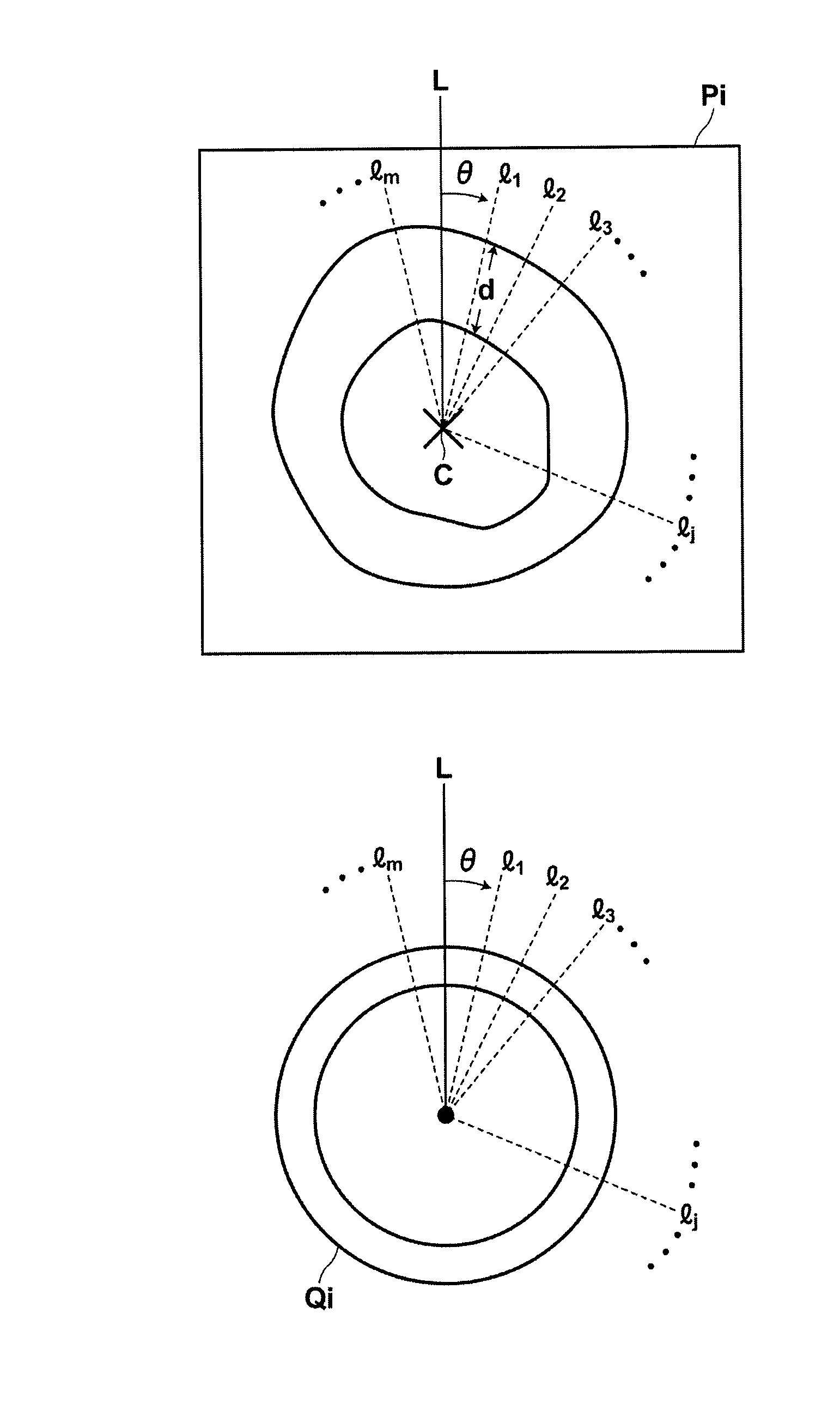
BACKGROUND OF THE INVENTION[0001]1. Field of the Invention[0002]The present invention relates to a cardiac function display apparatus for displaying a function of a heart and a program therefor.[0003]2. Description of the Related Art[0004]Heretofore, as a method for displaying a cardiac function, a bull's eye display method has been used. As illustrated in FIG. 2, the bull's eye display method is a method in which a heart is approximated with an ellipsoid model and images Q1, Q2, - - - Qi, - - - Qn representing evaluations of the cardiac function on planes P1, P2, - - - Pi - - - Pn provided by slicing the ellipsoid at a regular interval in a direction traversing the major axis of the ellipsoid are concentrically arranged and displayed (FIG. 13). In the bull's eye display method, the function on plane P1 near one of the major vertices of the ellipsoid model is disposed in Q1 located near the center of the concentric circles and the function on plane Pn near the other of the major ver...

Claims


Application Information

Patent Timeline
IPC IPC(8): G06K9/00
CPCA61B6/03A61B6/503A61B6/506G06T2207/10072G06T2207/30048G06T7/0026G06T7/32
Inventor MIYAMOTO, MASAKIMASUMOTO, JUNHIRANO, MASAHARUSAKURAGI, FUTOSHI
Owner FUJIFILM CORP
Learn More