Differential operational amplifier circuit correcting settling error for use in pipelined a/d converter
a technology of operating amplifier circuit and settling error, which is applied in the direction of differential amplifiers, amplifiers with semiconductor devices/discharge tubes, instruments, etc., can solve the problems of disadvantageous increase in power consumption, difficulty in designing analog circuits for obtaining reliable performances, and the necessity of complicated correction circuits, so as to facilitate the provision of a correction circuit and reduce the settling time , the effect of reducing the required accuracy of the settling error
Inactive Publication Date: 2010-03-25
SEMICON TECH ACADEMIC RES CENT
View PDF16 Cites 28 Cited by
- Summary
- Abstract
- Description
- Claims
- Application Information
AI Technical Summary
Benefits of technology
[0022]Au object of the present invention is to solve the above problems and provide a differential operational amplifier circuit capable of being employed for use in a high-resolution A / D converter of 14 bits or more and highly accurately correcting the settling error with a simple configuration compared to the prior art and a pipelined A / D converter that employs the differential operational amplifier circuit.
[0027]According to the differential operational amplifier circuit for use in the pipelined A / D converter of the present invention, linearly correcting the settling error is able not only to facilitate the provision of a correction circuit in the digital region but also to remarkably ease the required accuracy of the settling error. According to simulation results conducted by the present inventor and others, the settling time can be reduced by half, and therefore, the power consumption can be reduced to about half that of the prior art. The reason is that, if it is tried to reduce the settling error, then the bias current of the differential operational amplifier generally increases, and the power consumption disadvantageously increases. If the settling error itself can be digitally corrected, it obviates the need for increasing the bias current of the amplifier for reducing the settling error, and therefore, the required accuracy of the analog circuit is eased.
[0028]The non-slewing differential operational amplifier of the present invention, which has small static power consumption, however has a great driving ability in the case where the amplifier charges and discharges the capacitance. An output drive current being almost two or more times that of the conventional amplifier is obtained in the gm drive region, and a greater output drive current is obtained in the slewing region. In addition, the static power consumption is allowed to be about half that of a folded cascode amplifier since there are two unit bias current lines, and therefore, power efficiency is very high. The reason is that the amplifier is not of the constant current drive type but has push-pull operation (class AB operation).
Problems solved by technology
On the other hand, measures against deteriorations in signal to noise ratio (SNR) and so on due to element variations on processes and lowered voltages are necessary although the basic performances of transistors are improved, and this makes it difficult to design analog circuits for obtaining reliable performances.
A settling error, which is similarly an error factor, disadvantageously increases power consumption as a consequence of an increase in the bias current of an amplifier if it is generally tried to reduce the error.
However, since the settling error when a class-A amplifier with a constant current region is employed is nonlinear, there has been a problem of the necessity of a complicated correction circuit.
According to the this method, the incomplete settling is corrected as a second-order nonlinear function, a complicated correction circuit results with the necessity of a digital multiplier or the Me, and this therefore has led to a problem that the method is not suitable for high resolution of 14 bits or more.
Therefore, the settling response becomes a linear error in the first-order step response.
According to this method, odd-order (third and fifth) nonlinearities ascribed to the open loop architecture itself remain and a complicated correction circuit becomes necessary, and this therefore has led to a problem that the method is not suitable for high resolution of 14 bits or more.
According to this method, there has been a problem that an increase in the power consumption of the added comparators, an areal increase due to the added sampling capacitance and recovery of dynamic range in the digital region become necessary.
Method used
View moreImage
Smart ImageViewing Examples


Examples
embodiment
Modified Preferred Embodiment
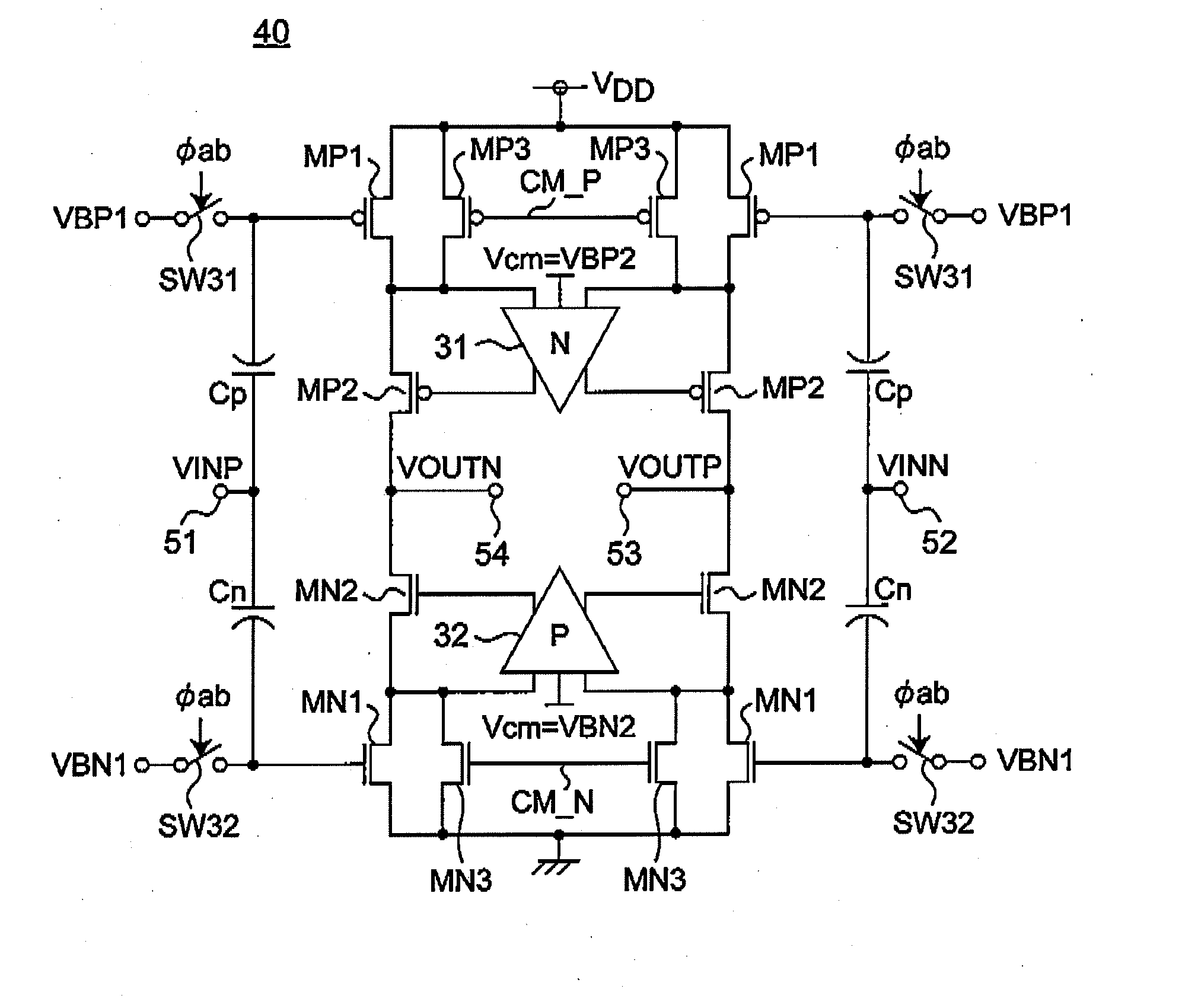
[0093]The auxiliary differential operational amplifiers 31 and 32, which are inserted for gain enhancement in the above preferred embodiment, may be removed when there is no need to enhance the gain
Login to View More PUM
 Abstract
A telescopic differential operational amplifier circuit for use in a pipelined A / D converter is provided with two auxiliary differential amplifiers connected to two cascode circuits, each including cascode-connected first to fourth transistors. During the sampling phase, first and second switches are turned on to apply a predetermined bias voltage to the gates of first and fourth transistors, and the input terminal of the differential operational amplifier circuit is set to a common mode voltage. During the hold phase, the first and second switches are turned off so that a voltage of each of the gates of the first and fourth transistors change to follow an input signal inputted via the input terminal with coupling capacitors operating as a level shifter of the input signal. Then the differential operational amplifier circuit performs push-pull operation operative only in a transconductance drive region, and is prevented from operating in a slewing region.
Description
BACKGROUND OF THE INVENTION[0001]1. Field of the Invention[0002]The present invention relates to a differential operational amplifier circuit that is employed for use in, for example, a pipelined A / D converter, where the differential operational amplifier corrects a settling error, and relates to a pipelined A / D converter that employs the differential operational amplifier circuit.[0003]2. Description of the Related Art[0004]In these days when analog-digital consolidation system LSIs play great roles with developments in communication systems and video technologies, reductions in power consumptions of analog circuits are major matters of concern. Advancements in semiconductor fine processing technologies have brought developments in performance and integration density of digital circuits and achieved efficient power reductions with lowered power supply voltages. On the other hand, measures against deteriorations in signal to noise ratio (SNR) and so on due to element variations on p...
Claims
Login to View More Application Information
Patent Timeline
 IPC IPC(8): H03M1/12H03F3/45
CPCH03F3/45237H03F2203/45094H03F2203/45551H03F2203/45481H03F2203/45356
Inventor KAWAHITO, SHOJIHONDA, KAZUTAKASHIMIZU, YASUHIDETANI, KUNIYUKIKURAUCHI, AKIRASUSHIHARA, KOJIMASHIKO, KOICHIRO
Owner SEMICON TECH ACADEMIC RES CENT
Features
- R&D
- Intellectual Property
- Life Sciences
- Materials
- Tech Scout
- Unparalleled Data Quality
- Higher Quality Content
- 60% Fewer Hallucinations
Learn More Browse by: Latest US Patents, China's latest patents, Technical Efficacy Thesaurus, Application Domain, Technology Topic, Popular Technical Reports.
© 2025 PatSnap. All rights reserved.Legal|Privacy policy|Modern Slavery Act Transparency Statement|Sitemap|About US| Contact US: help@patsnap.com