Ship with a special lower level

a technology of hull and lower level, applied in the field of ships, can solve the problems of lack of stability, plow-bow-shaped hull, few ships are practically adaptable to heavier ships, etc., and achieve the effects of improving maneuverability and efficiency, reducing pressure in the tunnel, and improving ship performan

Inactive Publication Date: 2010-03-25
KONSTANTINOVSKIY ALEXANDR
View PDF4 Cites 19 Cited by
  • Summary
  • Abstract
  • Description
  • Claims
  • Application Information

AI Technical Summary

Benefits of technology

[0015]Preferred embodiments of the ship further comprise at least one propeller. The propeller is positioned inside of the tunnel, so that the water that is fed to the propeller comes from the tunnel. This in turn reduces the pressure in the tunnel and improves ship's performance.
[0016]In order to improve maneuverability and efficiency, the ship preferably further comprises one or more front rudders. The rudders are positioned

Problems solved by technology

While many glider-type hull designs have been developed in recent decades, few of them are practically adaptable to heavier ships.
One major deficiency of the plow-bow-shaped hull is the lack of stability.
Long keels greatly increase the risk of ships running aground, and the risk of underwater collisions with submarines and mines (in areas of past or present military conflicts).
Ship keels are a great source of injury to large marine animals.
Large and heavy keels required for today's ships produce powerful frontal resistance and friction against water, reducing speed and increasing the power consumption.
Increased costs of shipping, caused by inefficient shipping vessels, translate to increased costs of imports, reduced exports and overall strain for the global economy.
Continued stress on the hull, resulting from the pitch also leads to reduced service life and increased maintenance costs of the vessels.
Even today, with cruise ships doubling in size every decade or so, many people suffer from sea sickness on cruise vacations.
Similarly, the roll and pitch on military ships, such as aircraft carriers, or cruise missle-launching ships may complicate takeoff and landing of aircraft,

Method used


Image

  • Ship with a special lower level
  • Ship with a special lower level
  • Ship with a special lower level

Examples


Embodiment Construction

[0026]The method of the present invention will now be illustrated by reference to the accompanying drawings.

[0027]Preferred embodiments of the new ship body of the present invention have been assigned reference numeral 10. Other elements have been assigned the reference numerals referred to below.

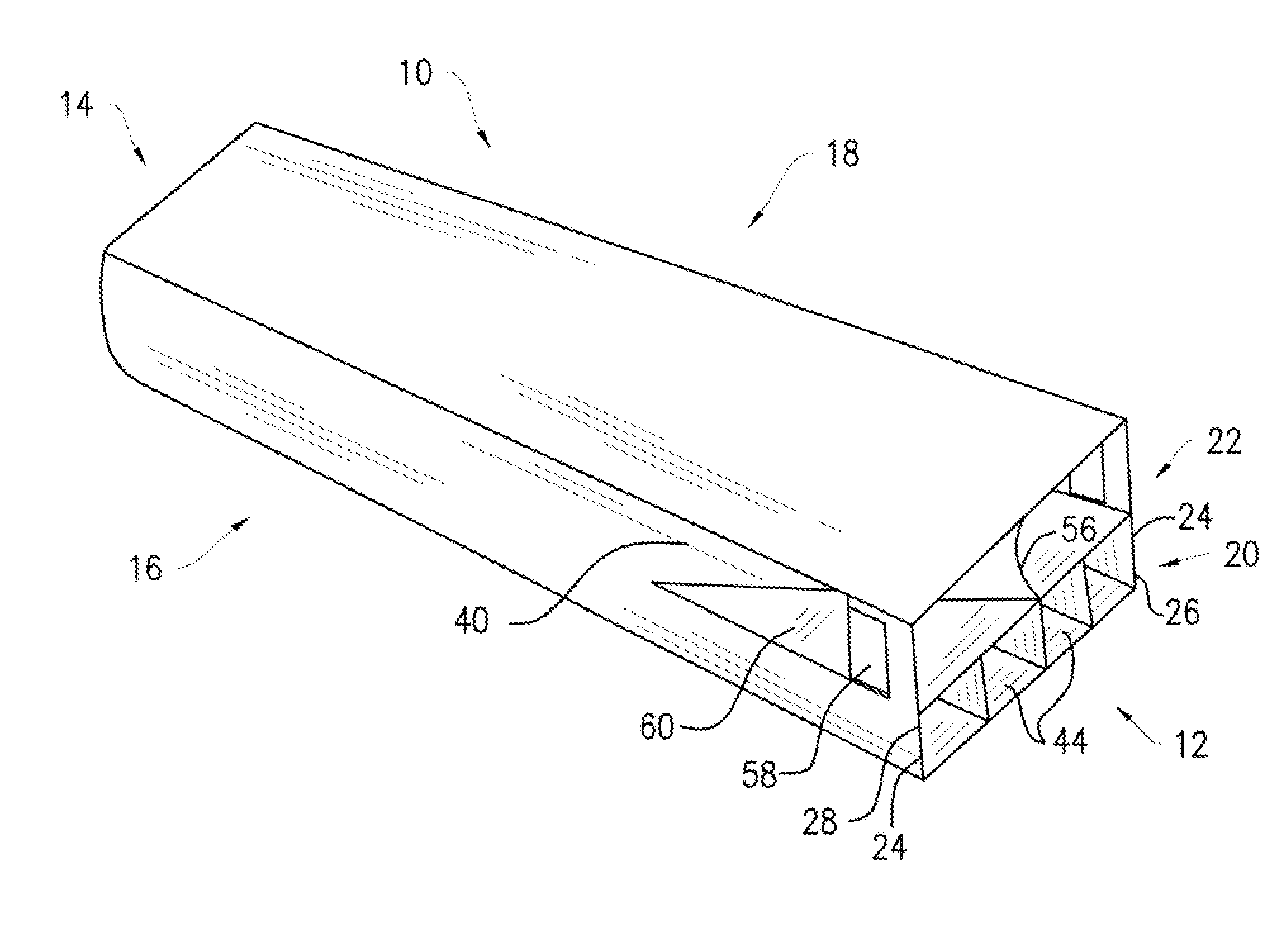
[0028]The ship body 10, also referred to as ship 10 and vessel 10 is directed to the new type of ship body that has at least two levels. As most ship bodies, ship 10 comprises a bow end 12, a stern end 14, a right side 16, and a left side 18, all marked for ease of reference on FIG. 1. The bow end 12 refers to the front section of the ship, the stern end 14, to the rear section of the ship, and the right side 16, and the left side 18, to the right and left side of the ship (not the drawing), respectively.

[0029]The ship 10 further comprises a lower level 20 and an upper level 22. The lower level 20 is one of the key elements of the design of the new vessel. It is the element that allows for ...


PUM


Abstract

The ship body of the present invention comprises at least two levels. One is an upper level that comprises a floatable body. The other is a lower level. The lower level is intended to be submerged under water in normal use. The lower level comprises at least two parallel, essentially vertical walls, a floor, and a ceiling connecting the at least two parallel essentially vertical walls. The front end and a rear end of the lower level are open to allow water to enter through the front end and exit through the rear end of the lower level.

Description

FIELD OF THE INVENTION[0001]The field of the present invention is ships and particularly a ship with a new type of hull, comprising a special lower level that provides stability and improves other characteristics of the ship.BACKGROUND OF THE INVENTION[0002]The shape of most modern ship hulls follows a long line of tradition, dating back hundreds if not thousands of years. As shipbuilding progressed from dugout canoes to triremes, to caravels, to ironclads, to modern hundred-thousand-ton cruise ships, many things changed. The size, modes of propulsion and construction materials have evolved, yet the same plow-shaped hull remains on the vast majority of today's displacement-type vessels. This is particularly true of the larger heavier boats plowing the oceans today, such as commercial transport ships, cruise ships and aircraft carriers.[0003]While many glider-type hull designs have been developed in recent decades, few of them are practically adaptable to heavier ships. The ships tha...

Claims


Application Information

Patent Timeline
IPC IPC(8): B63B1/38B63B3/00B63B3/56B63H5/16B63B43/04B63H25/38B63B19/08
CPCB63B1/042B63B1/38Y02T70/122B63B43/04B63B2241/02B63B3/00Y02T70/10
Inventor KONSTANTINOVSKIY, ALEXANDR
Owner KONSTANTINOVSKIY ALEXANDR
Why Eureka
Try Eureka