Apparatus for granulating plastic

a technology of granulating apparatus and plastic, which is applied in the field of granulating apparatus, can solve the problems of inability to achieve the effect of granulation, inability to achieve granulation, etc., and achieves the effect of simple construction conditions and increased flow resistan

Inactive Publication Date: 2010-03-18
ECON
View PDF32 Cites 3 Cited by
  • Summary
  • Abstract
  • Description
  • Claims
  • Application Information

AI Technical Summary

Benefits of technology

[0006]Since as a result of these measures the conveying and cooling medium is forced to flow from the feed chamber through the rotor into the gap region between die plate and rotor which is enclosed by the granulator blades, a radially outwardly directed conveying and cooling flow is obtained between the granulator blades, so that the granulate is conveyed in a secure manner from the rotor radially to the outside to the outfeed chamber and from there to the discharge. This arrangement of flow thus ensures a disturbance-free granulation process.
[0007]Although the flow connection between the feed chamber of the housing and the rotor plays an only subordinate role for the distribution of flow on the side of the discharge chamber, especially simple constructional conditions are obtained when the rotor comprises a coaxial jacket on the rear side facing the feed chamber, which jacket forms an annular chamber open towards the feed chamber for guiding the conveying and cooling medium, so that the conveying and cooling medium is conveyed with a distinct axial flow component to the rotor. In order to avoid having to provide any sealing of the jacket rotating with the rotor against the feed chamber, the jacket can protrude into the feed chamber with play through an opening of a separating wall perpendicular to the rotor shaft between the feed and the discharge chamber. The play of the jacket of the rotor within the opening of the separating wall between the feed and the discharge chamber not only entails simple constructional conditions, but also causes a flow passage from the feed to the discharge chamber outside of the rotor, leading to the advantage that the otherwise obtained dead flow spaces within the discharge chamber are flushed after the rotor. This flushing prevents the deposit of granulate particles in said dead spaces.
[0008]The granulator blades are usually applied with a predetermined pressure against the die plate. Since the gap will decrease between the die plate and the rotor pressurized accordingly in the axial direction in the case of wear and tear of the blades, the flow resistance will increase for the conveying and cooling medium flowing through the rotor, leading to an increased flow of the conveying and cooling medium outside of the rotor in the case of play between the jacket of the rotor and the opening in the separating wall. In order to ensure that actions thus caused on the radial conveyance of granulate from the region of the granulating head are prevented, the jacket can taper conically against the rotor at least in the region of its passage through the opening of the separating wall, so that the flow cross section also formed by the play of the jacket within the opening of the separating wall will decrease with the reduction of the flow cross section in the region of the gap between the die plate and the rotor and accordingly the division of the flow remains the same to a sufficient extent.

Problems solved by technology

Since the cooling fluid vertically flows through the housing accommodating the granulating head with die plate and rotor while the rotor shaft extends transversally to the direction of flow, there is the likelihood, as a result of gravity, that the granulate will reach the gap between the die plate and the rotor which is enclosed by the blades arranged in a circular way and will remain there, leading to malfunctions in the granulation.
Comparable difficulties can also occur with the use of air as a conveying and cooling medium.
Although it is already known (DE 197 20 722 A1) to feed the conveying and cooling medium in an axial manner to the housing which accommodates the rotor, the illustrated difficulties will remain because the conveying and cooling medium is introduced via a coaxial feed chamber into the housing on the side of the rotor which is averted from the granulator blades, so that the conveying and cooling medium is displaced via the rotor radially to the outside and cannot exert any conveying action on the granulate collecting within the circle of blades.

Method used


Image

  • Apparatus for granulating plastic
  • Apparatus for granulating plastic
  • Apparatus for granulating plastic

Examples


Embodiment Construction

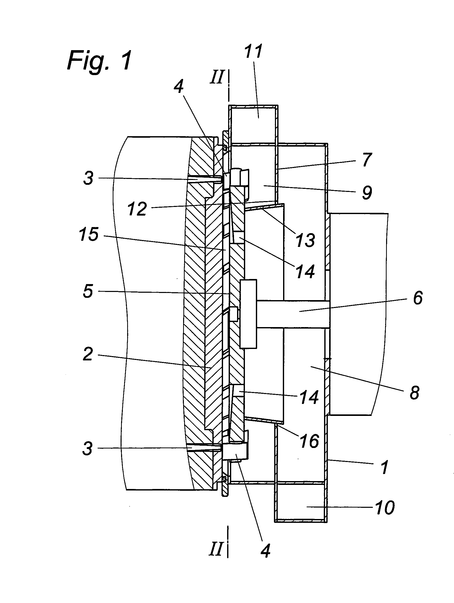
[0011]The illustrated apparatus comprises a housing 1 which is sealed on one face side by a die plate 2, with outlet nozzles 3 opening into its region through which a plastic melt will exit in a respective number of strands. The strands of plastic exiting in the region of each outlet nozzle 3 are cut with the help of granulator knives 4 into a plastic granulate, which knives are arranged on a rotor 5 which is coaxial to the die plate. The drive shaft 6 for the rotor 5 is guided in a conventional manner through the opposite face side of housing 1.

[0012]In contrast to conventional apparatuses of this kind, the housing 1 is subdivided by a separating wall 7 perpendicular to the rotor shaft 6 into a feed chamber 8 and a discharge chamber 9. These chambers 8 and 9 are connected to a feed 10 and a discharge 11 for a cooling fluid, usually water. The separating wall 7 forms an opening 12 which is coaxial to the rotor shaft 6 and through which protrudes a jacket 13 with play which is fasten...


PUM

PropertyMeasurementUnit
gravityaaaaaaaaaa
pressureaaaaaaaaaa
flow resistanceaaaaaaaaaa

Abstract

An apparatus for granulating plastic is described, comprising a granulating head having a die plate (2) for allowing the output of strands of plastic and a rotor (5) which is coaxial to the die plate (2) and comprises granulator blades (4) for cutting strands of plastic exiting from the die plate (2), and a housing (1) for the granulating head which is connected to a discharge line (11) and a feed line (10) via a feed chamber (8) for a conveying and cooling medium receiving the granulate, preferably a cooling fluid. In order to provide advantageous conveying conditions for the granulate it is proposed that the housing (1) forms a discharge chamber (9) which is separate from the feed chamber (8) for the conveying and cooling medium, the rotor (5) which is arranged between the feed chamber (8) and the discharge chamber (9) and which carries the granulator blades (4) is adjacent to the feed chamber (8) with its rear side averted from the granulator blades (4) and is provided within the circular blade arrangement with axial openings (14) for the passage of the conveying and cooling medium from the feed chamber (8) to the discharge chamber (9).

Description

FIELD OF THE INVENTION[0001]The invention relates to an apparatus for granulating plastic, comprising a granulating head, a die plate for allowing the output of strands of plastic and a rotor which is coaxial to the die plate and comprises granulator blades for cutting strands of plastic exiting from the die plate, and a housing for the granulating head which is connected to a discharge line and a feed line via a feed chamber for a conveying and cooling medium receiving the granulate, preferably a cooling fluid.DESCRIPTION OF THE PRIOR ART[0002]For the purpose of granulating plastic materials, a plastic melt is usually pressed in the form of strands of plastic through a die plate which cooperates with a rotor which is coaxial to the die plate and is equipped with granulator blades, so that the strands of plastic which are output to a cooling fluid, preferably water, are cut. The cooling fluid ensures a solidification of the plastic granulate on the one hand and its further conveyanc...

Claims


Application Information

Patent Timeline
Patent Type & Authority Applications(United States)
IPC IPC(8): B28B11/16
CPCB29B9/06B29B9/065B29C48/0022B29C48/05B29C48/04B29C48/345
Inventor PIRKER, STEFANGITTLER, PHILIPP
Owner ECON
Why Eureka
Try Eureka