
Structure determination system, structure determination method, and program

Inactive Publication Date: 2010-03-18
NAT INST OF ADVANCED IND SCI & TECH
View PDF12 Cites 11 Cited by
  • Summary
  • Abstract
  • Description
  • Claims
  • Application Information

AI Technical Summary

Benefits of technology

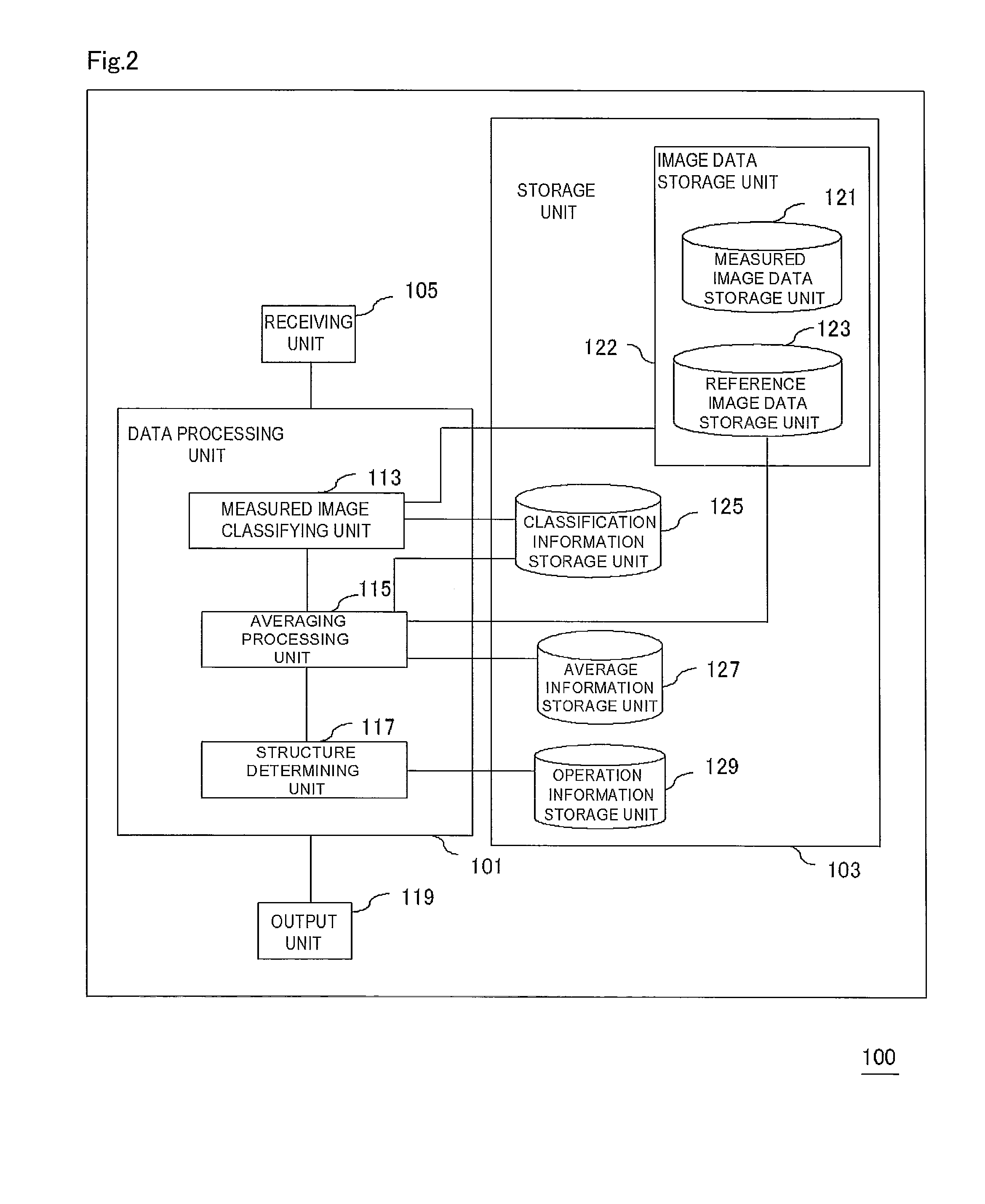
[0057]According to the present invention, data representing derived image groups which include a plurality of derived images obtained by changing a relative position to each reference image is generated for each of a plurality of measured images. Derived images that are highly similar to reference images are extracted from the derived image group for each measured image so as to improve the resolution of structural analysis using image data.

Problems solved by technology

This technique, however, requires crystallization of the sample, and cannot be applied to analysis of samples such as membrane proteins that are difficult to crystallize.

Method used


Image

  • Structure determination system, structure determination method, and program
  • Structure determination system, structure determination method, and program
  • Structure determination system, structure determination method, and program

Examples


example 1

[0210]In the present example, image analysis was performed using MRMA (optimum image searching using a plurality of image peaks) / MSA (multi-distributed static analysis) / HAC (hierarchical classification) methods sequentially.

[0211]The entire three-dimensional parameter space was searched for using the above-described method according to the embodiment described above, and for each measured image, a correlation value was computed while changing a relative position of a measured image and a reference image, a reference image which has a maximum peak of a correlation value was extracted, and reference images which correspond to all peaks within 10% from a maximum peak of a correlation value were extracted. One or more derived images were generated from one measured image based on the extracted reference image and its relative position. In order to make the accuracy identical to that of the comparative example 1 which will be described later, hierarchical processing was performed until a...

example 2

[0224]In the present example, about TRP3 protein, the entire three-dimensional parameter space was searched according to the method of the example 1 using 2,967 measured images (the number of pixels: 140×140), and about each measured image, a correlation value was computed while changing a relative position of a measured image and a reference image, a reference image which has a maximum peak of a correlation value was extracted, and reference images which correspond to all peaks within 10% from a maximum peak of a correlation value were extracted. The output number of reference images was 10,197. One or more derived images were generated from one measured image based on the extracted reference image and its relative position. Hierarchical processing was performed until a value of a final increment of distribution becomes a value which corresponds to a final increment of distribution when performing hierarchical classification up to a class in which 30 derived images were obtained in...


PUM


Abstract

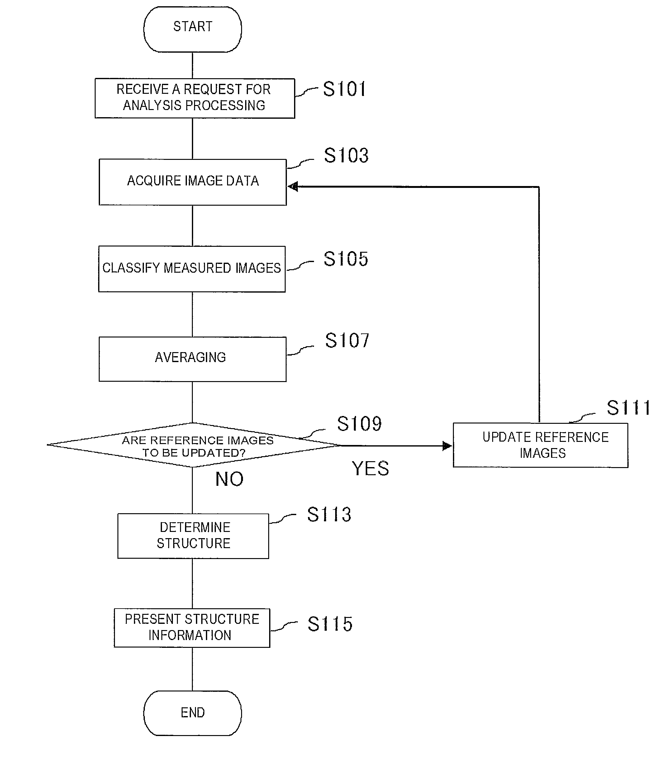
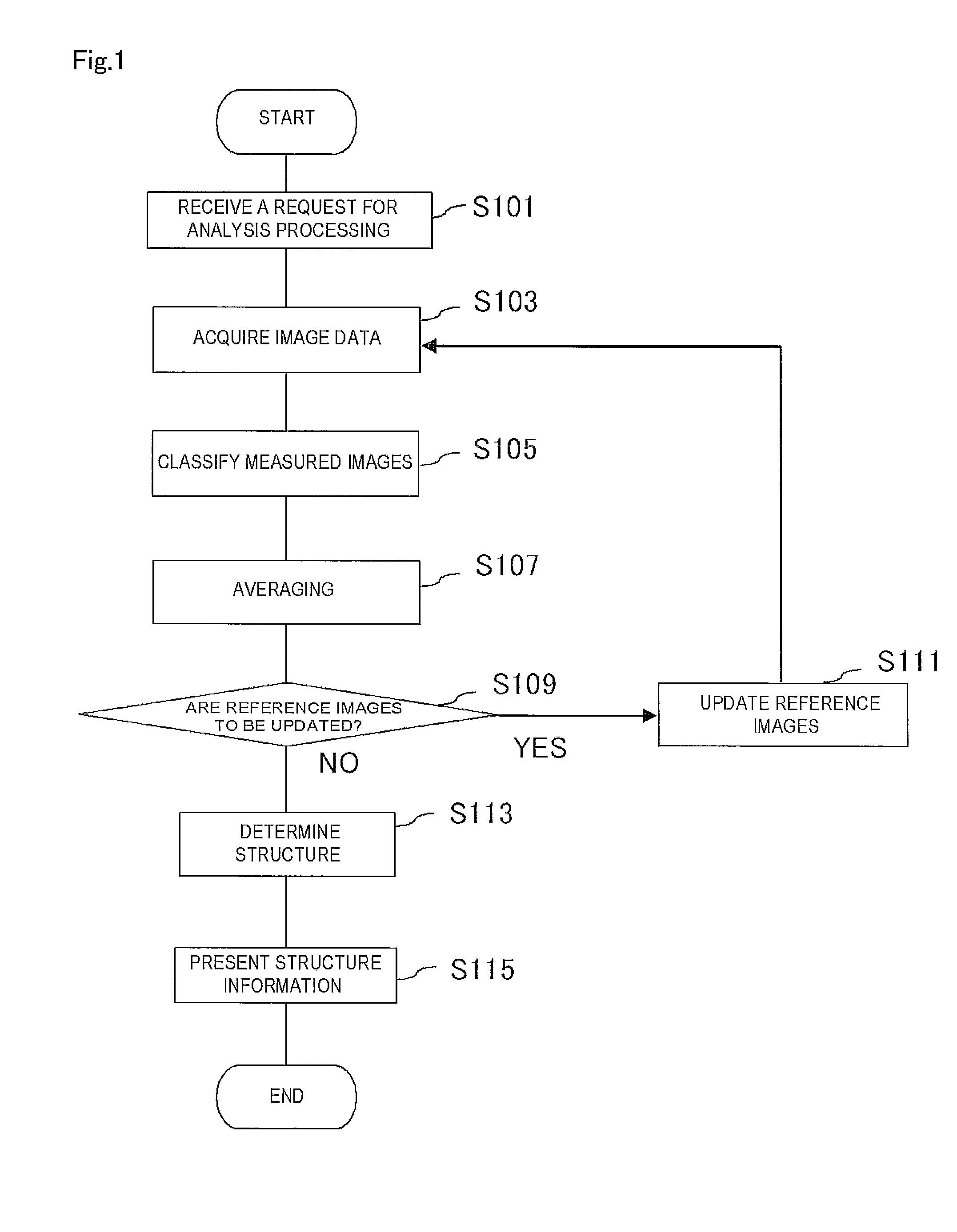
Resolution of structural analysis using image data is improved. A method is provided including the steps of: acquiring data representing measured images and data representing a predetermined number of reference images (S103); generating data representing groups of derived images by changing a relative position of each of the measured images, evaluating similarity between the derived images and the reference images for each group of the derived images, and extracting a plurality of derived images highly similar to any one of the reference images, from each of the groups of the derived images (S105); classifying the extracted derived images into a plurality of groups on the basis of a spatial arrangement of the derived images, averaging the derived images classified into a common group to generate data representing a plurality of averaged images (S107); and determining a structure of a measurement object based on data representing the averaged images (S115).

Description

TECHNICAL FIELD[0001]The present invention relates to a system, method and program for determining a structure of a subject of analysis based on image data.BACKGROUND ART[0002]A conventional technique of preparing, as a subject of analysis, a sample obtained by crystallizing biological macromolecules such as proteins, and analyzing and evaluating the sample using X-ray crystal structural analysis and NMR methods exists as a technique for analyzing the three-dimensional structure of molecules. This technique, however, requires crystallization of the sample, and cannot be applied to analysis of samples such as membrane proteins that are difficult to crystallize.[0003]Single particle structural analysis has been proposed as a technique which requires no crystallization of the sample in which a structure of proteins is analyzed using a Cryo-Transmission Electron Microscope (TEM) (see Non-Patent Documents 1 and 2). Single particle structural analysis is a method for extracting sample ima...

Claims


Application Information

Patent Timeline
IPC IPC(8): G06K9/62G01N23/225G06F19/16H01J37/22
CPCG06F17/30262G06K2209/403G06K9/00134G06F16/5862G06V20/693G06V2201/122
Inventor KAWATA, MASAAKISATO, CHIKARA
Owner NAT INST OF ADVANCED IND SCI & TECH
Learn More