
Method and System for LLR Buffer Reduction in a Wireless Communication Modem

a wireless communication modem and buffer reduction technology, applied in amplitude demodulation, coding, code conversion, etc., can solve the problems of high implementation complexity and high power consumption of high-performance demodulators such as maximum likelihood demodulators for 16 qam, 64 qam and 256 qam, so as to reduce the amount of llr buffer memory required, prevent the excess of llr buffer memory capacity, and improve performance.

Active Publication Date: 2010-03-18
QUALCOMM INC
View PDF17 Cites 17 Cited by
  • Summary
  • Abstract
  • Description
  • Claims
  • Application Information

AI Technical Summary

Benefits of technology

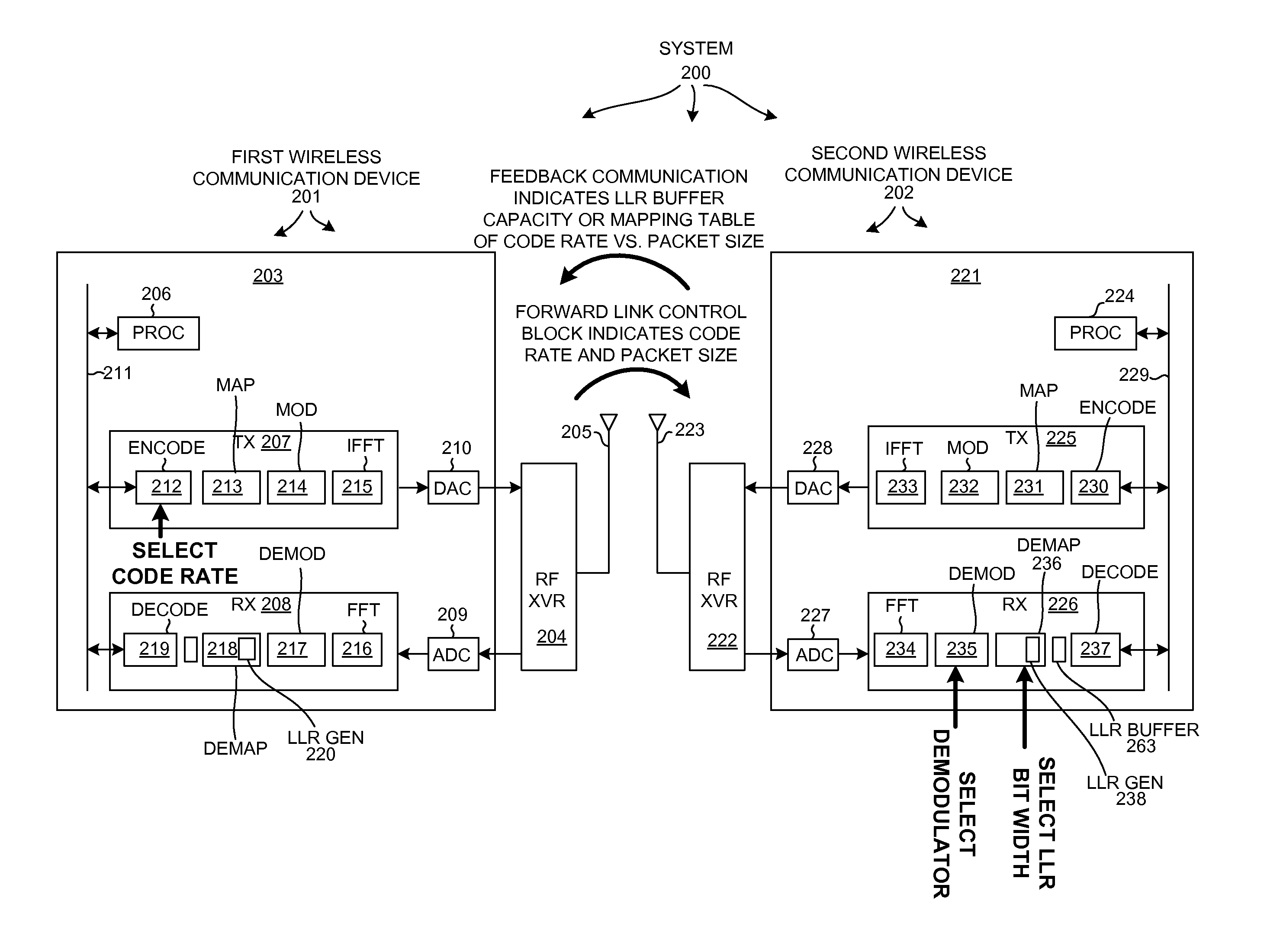
[0011]In a first aspect, LLR bit width is adjusted in the receiving device as a function of the packet size of an incoming transmission in order to reduce the amount of LLR buffer memory required and / or to prevent LLR buffer memory capacity from being exceeded. The processor of the receiver may receive a communication from the transmitter that informs the receiver of the packet size being used. In one example of the first aspect, the receiver uses a higher performance demodulator in order to maintain a desired performance despite the use of smaller LLR bit widths. For example, using a higher performance demodulator may be possible in cases where packets use a lower modulation order such as QPSK. In such cases, a higher-performance demodulator such as a Maximum Likelihood (ML) demodulator may be easy to implement, and may have power consumption characteristics similar to that of a lower performance demodulator such as an MMSE demodulator. If the higher performance demodulator (such as an ML demodulator) is impractical due to high implementation complexity or high power consumption, then a lower performance demodulator that consumes less power is used in order to reduce power consumption of the receiver. Typically, higher performance demodulators such as Maximum Likelihood demodulators for 16 QAM, 64 QAM and 256 QAM have high implementation complexity and high power consumption. In addition to adjusting LLR bit width in the receiver as a function of packet size, LLR bit width in the receiver can be adjusted as a function of one or more of the following: encoder code rate, number of interlaces and the LLR buffer size.
[0012]In a second aspect, encoder code rate in the transmitter is adjusted as a function of receiver LLR buffer capacity and of packet size of the outgoing transmission such that receiver LLR buffer capacity is not exceeded. The transmitter may receive a communication from the receiver that informs the transmitter of the LLR buffer storage capacity in the receiver. Or, the receiver may instead transmit a mapping table to the transmitter. The transmitter, in such a case, uses the mapping table to determine transmit parameters such that the receiver LLR buffer capacity is not exceeded. Any combination of receiver LLR bit width adjustment, demodulator selection, and encoder code rate adjustment can be practiced to prevent receiver LLR buffer storage capacity from being exceeded while at the same time maintaining system performance. The first and second aspects can be employed to reduce the amount of LLR buffer memory provided in a wireless communication device such that manufacturing cost of the wireless communication device is reduced.

Problems solved by technology

Typically, higher performance demodulators such as Maximum Likelihood demodulators for 16 QAM, 64 QAM and 256 QAM have high implementation complexity and high power consumption.

Method used


Image

  • Method and System for LLR Buffer Reduction in a Wireless Communication Modem
  • Method and System for LLR Buffer Reduction in a Wireless Communication Modem
  • Method and System for LLR Buffer Reduction in a Wireless Communication Modem

Examples


Embodiment Construction

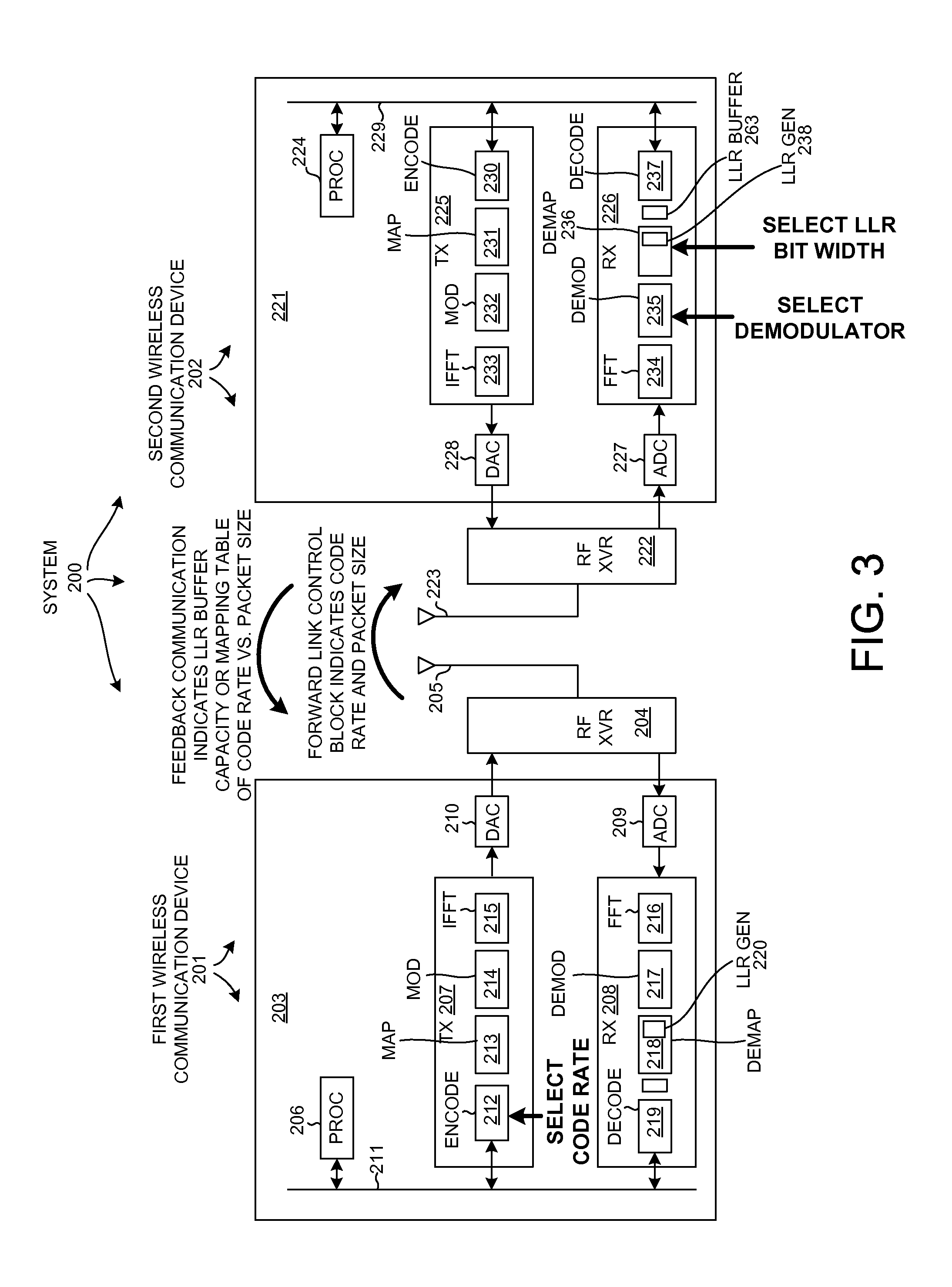
[0028]FIG. 3 is a simplified high level block diagram of a system 200 involving a first wireless communication device 201 and a second wireless communication device 202. Wireless communication devices 201 and 202 may, for example, be a base station and a cellular telephone. First wireless communication device 201 includes a digital baseband integrated circuit 203, a radio-frequency transceiver integrated circuit (RF XVR) 204 and an antenna 205. Digital baseband integrated circuit 203 includes a processing circuit 206, a transmit channel (TX) 207, a receive channel (RX) 208, an Analog-to-Digital Converter (ADC) 209, a Digital-to-Analog Converter (DAC) 210, and a bus 211. Transmit channel 207 includes an encoder circuit (ENCODE) 212, a map circuit (MAP) 213, a modulator circuit (MOD) 214, and an Inverse Fast Fourier Transform circuit (IFFT) 215. Receive channel 208 includes a Fast Fourier Transform circuit (FFT) 216, a demodulator circuit (DEMOD) 217, a demap circuit (DEMAP) 218, and ...


PUM


Abstract

A system involves a transmitting device (for example, a first wireless communication device) and a receiving device (for example, a second wireless communication device). In the receiving device, LLR (Log-Likelihood Ratio) values are stored into an LLR buffer. LLR bit width is adjusted as a function of packet size of an incoming transmission to reduce the LLR buffer size required and / or to prevent LLR buffer capacity from being exceeded. The receiver may use a higher performance demodulator in order to maintain performance despite smaller LLR bit width. In the transmitting device, encoder code rate is adjusted as a function of receiver LLR buffer capacity and packet size of the outgoing transmission such that receiver LLR buffer capacity is not exceeded. Any combination of receiver LLR bit width adjustment, demodulator selection, and encoder code rate adjustment can be practiced to reduce LLR buffer size required while maintaining performance.

Description

CROSS-REFERENCE TO RELATED APPLICATION[0001]This application claims the benefit under 35 U.S.C. §119 of Provisional Application Ser. No. 61 / 039,775, filed Mar. 26, 2008, said provisional application is incorporated herein by reference.BACKGROUND INFORMATION[0002]1. Technical Field[0003]The present disclosure relates to managing parameters that affect the amount of buffer memory space used to store Log-Likelihood Ratio (LLR) values in a receiver.[0004]2. Background Information[0005]In communication systems, such as cellular telephone systems, information is often to be communicated between devices in the presence of noise and other environmental factors that interfere with the communication. To prevent loss of information, the original information to be communicated is often encoded along with additional information before transmission. After reception, the received information is decoded to recover the original information. Due to the encoding and decoding process, if some of the tr...

Claims


Application Information

Patent Timeline
Patent Type & Authority Applications(United States)
IPC IPC(8): H04L5/12H04L27/06
CPCH03M13/45H03M13/6588H04L25/067H04L1/1819H04L5/0007H04L1/0046H04L1/1822H04L1/1835H04L1/1845
Inventor SAMPATH, HEMANTHAGRAWAL, AVNEESHLIN, JEREMY H.
Owner QUALCOMM INC
Learn More