
Wireless communication device, method to output identifier, and computer usable medium therefor

Inactive Publication Date: 2010-03-18
BROTHER KOGYO KK
View PDF16 Cites 45 Cited by
  • Summary
  • Abstract
  • Description
  • Claims
  • Application Information

AI Technical Summary

Benefits of technology

[0008]In view of the above drawbacks, the present invention is advantageous in that a wireless communication device, in which the network identifiers are presented effectively to the user, is provided. Further, a method to output the identifiers and a computer usable medium therefor are provided.

Problems solved by technology

When a plurality of wireless networks are available, and a large number of identifiers of the networks such as the SSIDs are detectable by the communication device, however, the user may be troubled by the large numbers of available options, and the user may not find a desirable network identifier easily.

Method used


Image

  • Wireless communication device, method to output identifier, and computer usable medium therefor
  • Wireless communication device, method to output identifier, and computer usable medium therefor
  • Wireless communication device, method to output identifier, and computer usable medium therefor

Examples


first embodiment

[0023]Hereinafter, a first embodiment according to an aspect of the present invention will be described with reference to the accompanying drawings.

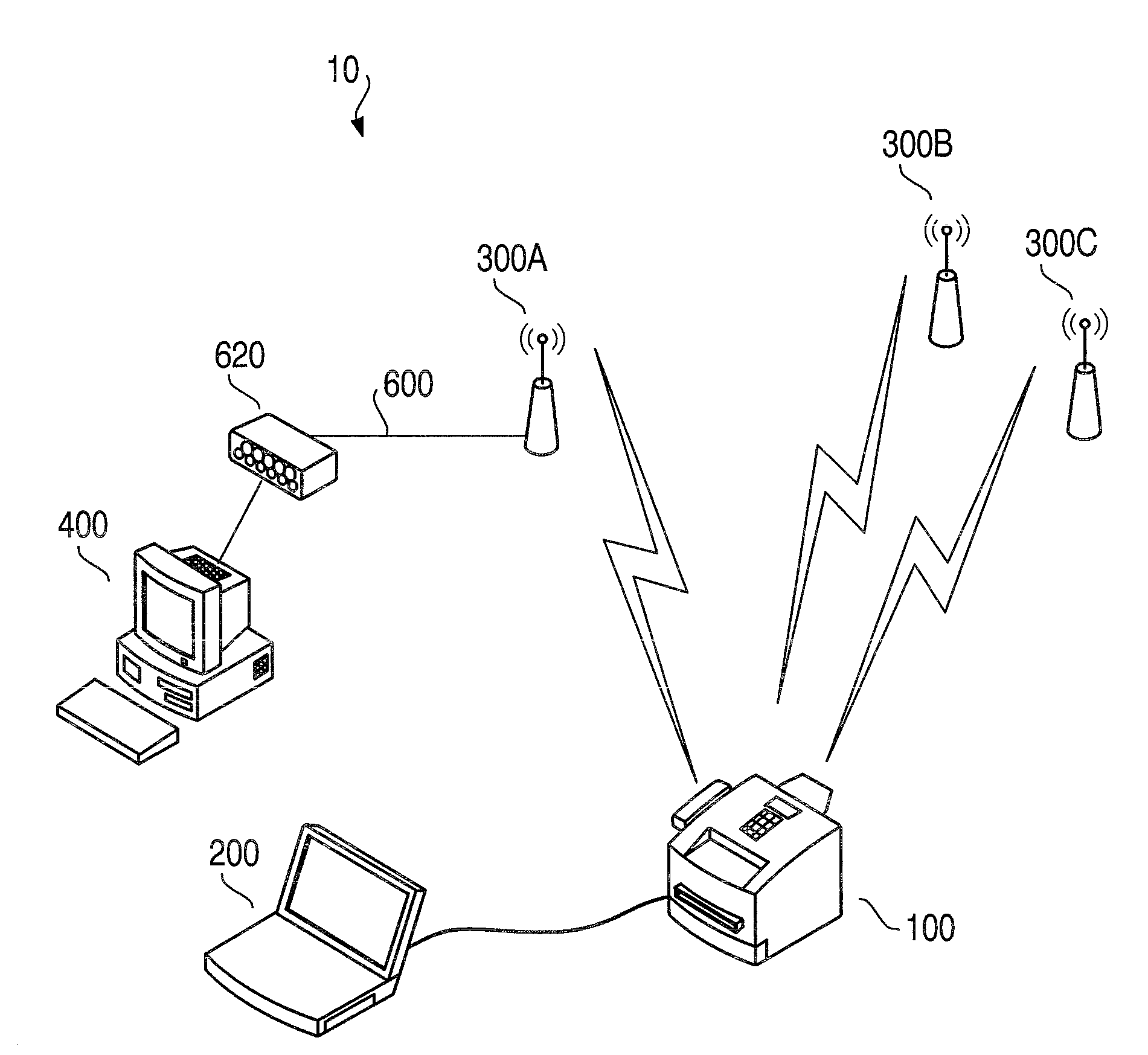
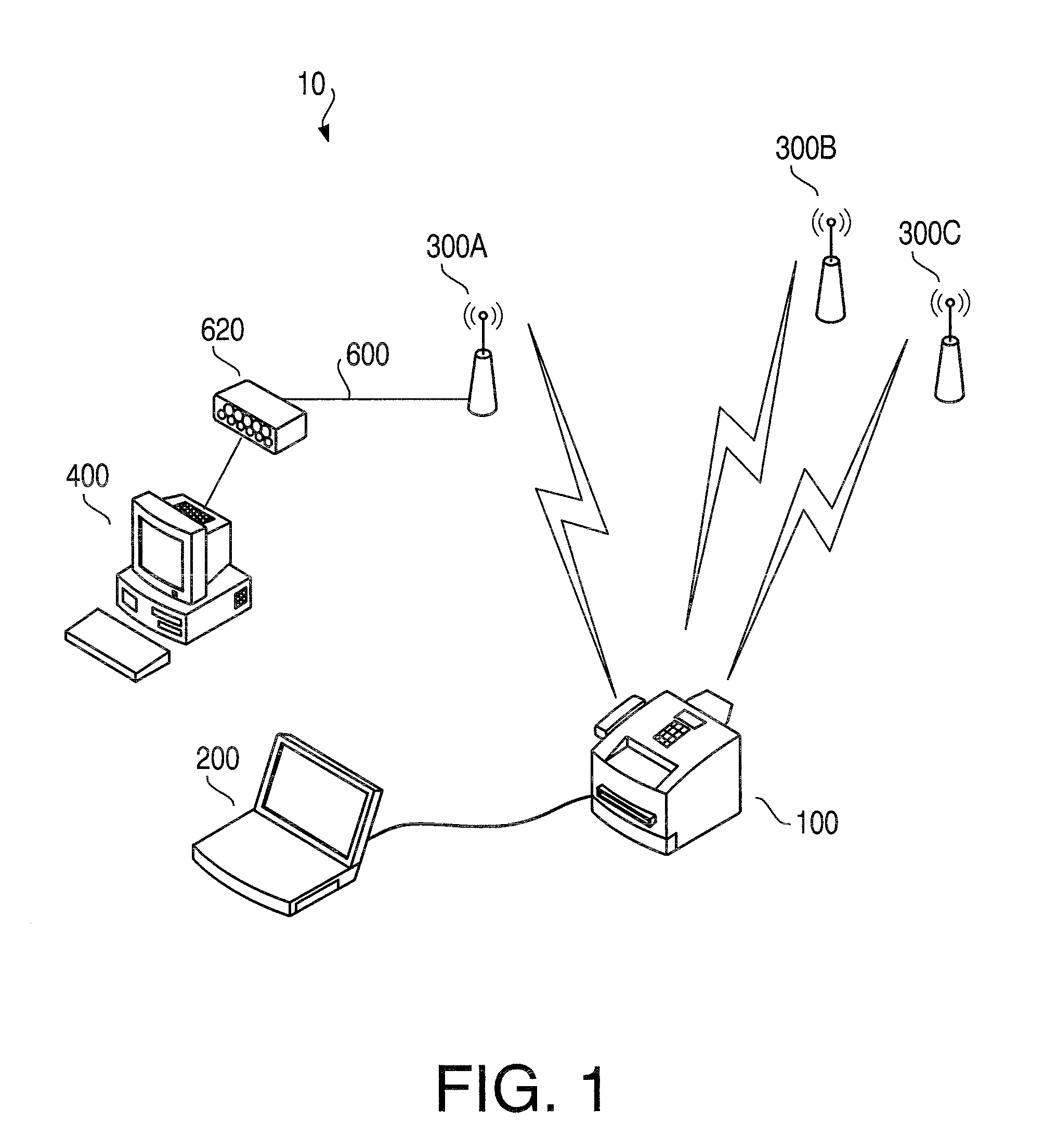
[0024]Firstly, an overall configuration of a network system including a wireless network 10 according to the embodiment of the present invention will be described. FIG. 1 is a schematic diagram to illustrate the network system according to the embodiment of the present invention. The wireless network 10 includes an access point 300A and an MFP (multifunction peripheral) 100. The MFP 100 is equipped with a plurality of functions to, for example, print, scan, and / or copy images. The MFP 100 is connected to a PC (personal computer) 400 within the wireless network 10 through the access point 300A, a wired LAN 600, and a hub 620. The MFP 100 can receive print data transmitted from the PC 400 to print and transmits image data representing a scanned image to the PC 400.

[0025]The wireless network 10 further has a plurality of access points, incl...

second embodiment

[0054]Next, the present invention will be described with reference to FIGS. 12-14.

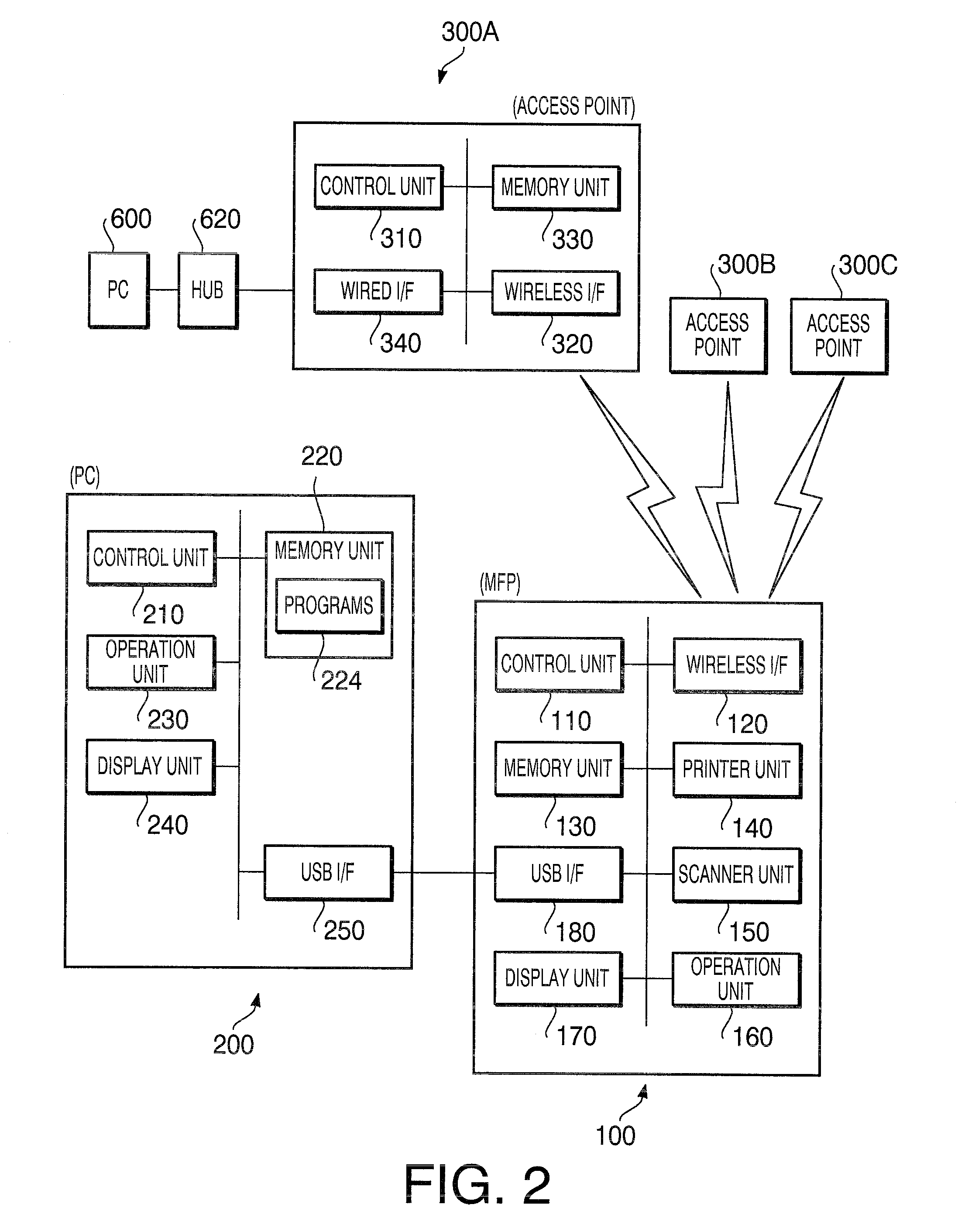
[0055]FIG. 12 is a flowchart to illustrate a second wireless setting installation process according to the second embodiment of the present invention. In the present embodiment, the user's instructions to install the wireless settings in the MFP 100 is entered through the PC 200 which is connected to the MFP 100 through the USB interfaces 180, 250 (see FIGS. 1 and 2).

[0056]When the second wireless settings installation process starts, i.e., when the control unit 210 of the PC 200 detects the user's instruction to start the second wireless settings installation process through the operation unit 230, in S500, the control unit 210 activates a program 224 stored in the memory unit 220. Further, the control unit 210 controls the USB interface 250 to transmit an SSID search request to the MFP 100 so that the MFP 100 activates an SSID searching operation (S600). During the SSID searching operation, the statu...


PUM


Abstract

A wireless communication device capable of outputting an identifier of an existing wireless network to an output unit is provided. The wireless communication device includes an identifier obtaining unit to obtain identifiers from a plurality of access points, a judging unit to judge whether each of the access points operates in a specific operation mode based on each of the obtained identifiers, a determining unit to determine an identifier is a first identifier if the access point which provided the identifier does not operate in the specific operation mode, and determine the identifier is a second identifier if the access point which provided the identifier operates in the specific operation mode, and an output control unit to output the first identifier to the output unit, such that the first identifier is shown by the output unit in a manner that the first identifier is distinguished from the second identifier.

Description

CROSS REFERENCE TO RELATED APPLICATION[0001]This application claims priority from Japanese Patent Application No. 2008-237408, filed on Sep. 17, 2008, the entire subject matter of which is incorporated herein by reference.BACKGROUND[0002]1. Technical Field[0003]An aspect of the present invention relates to a wireless communication device to be connected to a network. More specifically, the present invention relates to a technique to output identifiers which identify networks to be recognizable by a user.[0004]2. Related Art[0005]Wireless LAN (local area network) has been widespread and utilized in network computing environment. Hereinafter, a wireless network refers to the wireless LAN. In the network computing environment, a plurality of wireless LANs can be settled in an area. When a communication device is connected to one of the wireless networks, the communication device is required to have predetermined wireless settings installed. For example, when the communication device is...

Claims


Application Information

Patent Timeline
IPC IPC(8): H04L12/28
CPCH04W48/16
Inventor SUZUKI, TAKANOBU
Owner BROTHER KOGYO KK
Learn More