
Position guiding device, position guiding method, and position guiding program

Active Publication Date: 2017-03-02
KK TOPCON
View PDF8 Cites 10 Cited by
  • Summary
  • Abstract
  • Description
  • Claims
  • Application Information

AI Technical Summary

Benefits of technology

The patent text describes a technique for guiding an operator to a specific position. However, sometimes it can be difficult to confirm the exact position in the actual field. The objective of the patent is to provide a position guiding device, method, and program that make it easier and more accurate for operators to confirm their target position.

Problems solved by technology

In the above procedure, it is, however, not easy and convenient to move the collimation target to the predetermined horizontal coordinate position.

Method used


Image

  • Position guiding device, position guiding method, and position guiding program
  • Position guiding device, position guiding method, and position guiding program
  • Position guiding device, position guiding method, and position guiding program

Examples


embodiment

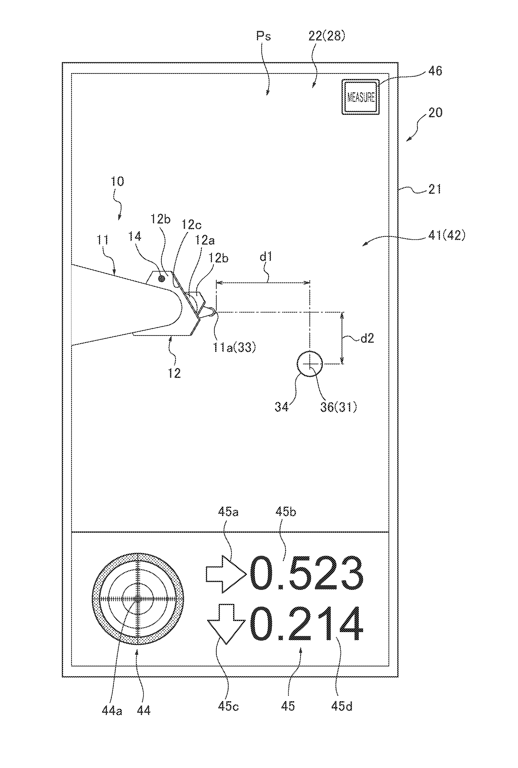
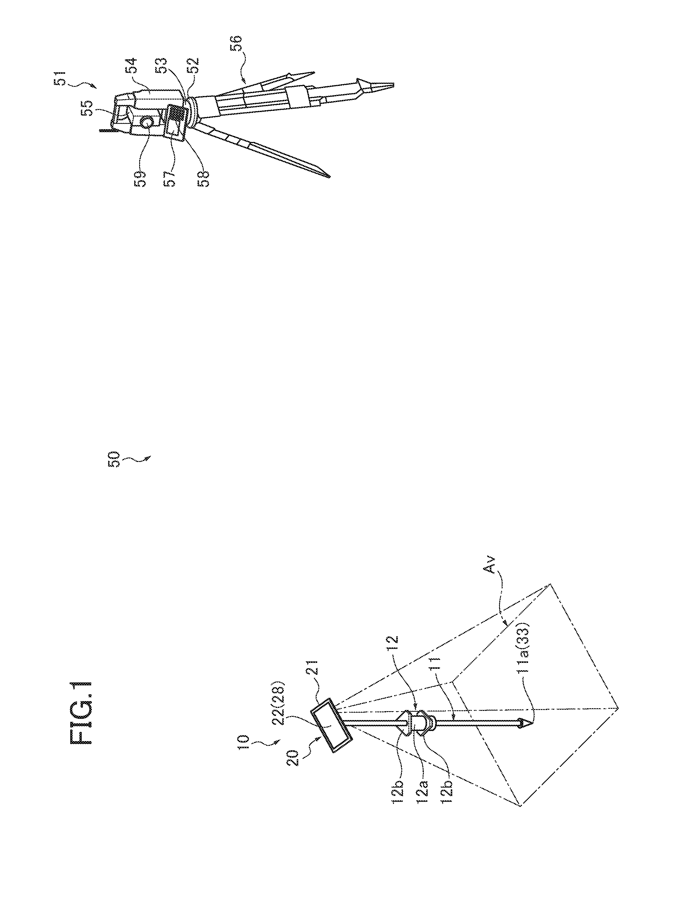
[0023]First, a schematic configuration of a survey system 50 using a position guiding device 10 according to an embodiment of the present invention will be described. As illustrated in FIG. 1, the survey system 50 guides an operator W (shown in FIG. 10) having the position guiding device 10 from a position (current position) of the position guiding device 10 detected by a surveying instrument 51 to a target position (e.g., an surveying point Sp (shown in FIG. 10)). With this, the survey system 50 allows the operator W to confirm the target position (e.g., a surveying point Sp) accurately. The position guiding device 10 is configured such that the operator W can easily confirm the target position accurately. Note that the target position is indicated with a three-dimensional coordinate.

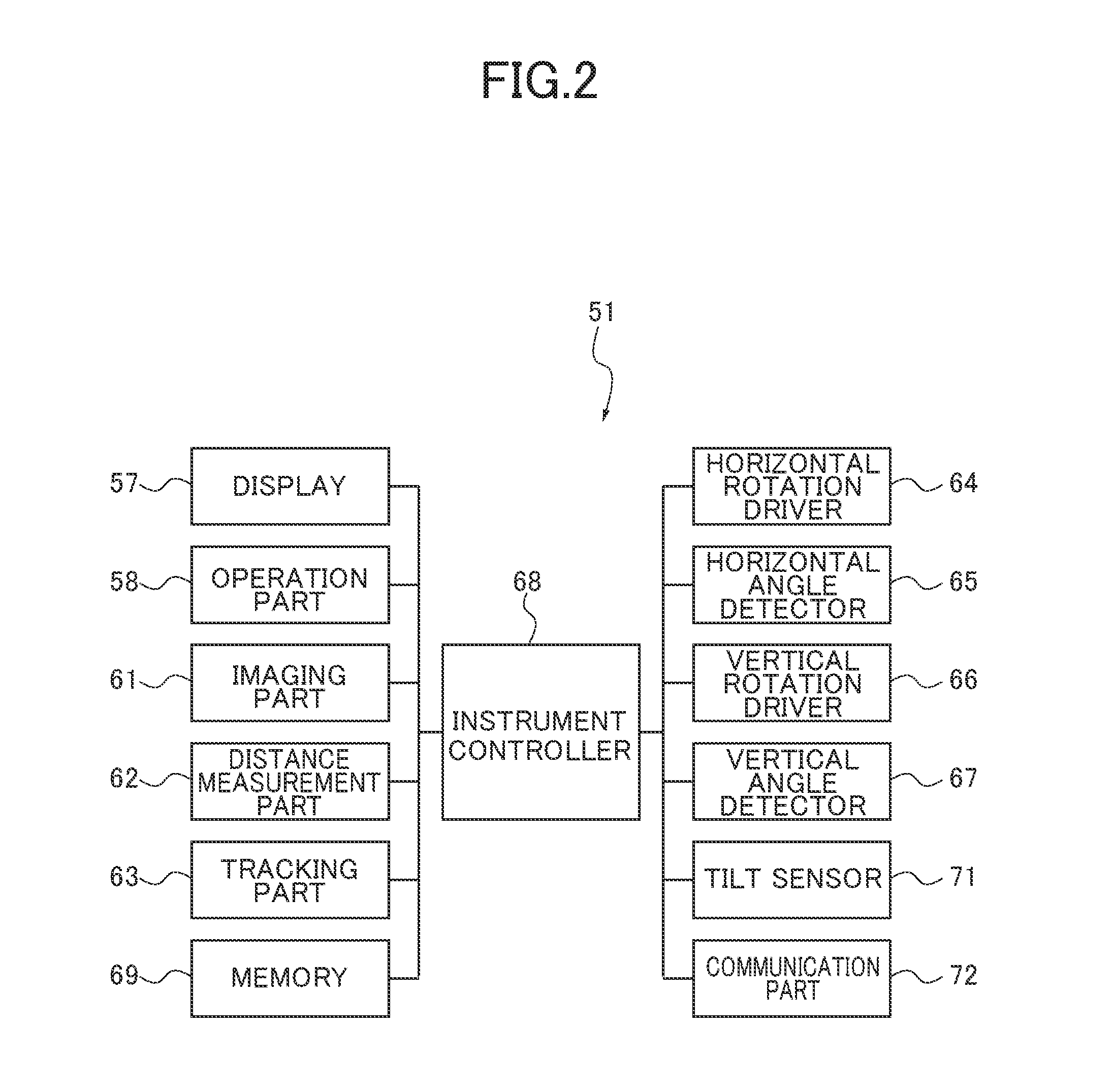
[0024]In the embodiment, the surveying instrument 51 is configured as a total station and is installed at a known point. The surveying instrument 51 emits a pulse laser to a measurement point, receives...


PUM


Abstract

A position guiding device includes a mobile terminal having an imaging part and display, a position information acquiring part for acquiring current coordinate information and target coordinate information, a direction sensor for acquiring direction information, and a controller to generate a target image. The mobile terminal is attached to a pole so as to position a pole tip within an angle of view. The controller acquires, from the position information acquiring part, current coordinate information representing a position at where the pole tip points, defines a horizontal surface including the pole tip as a measurement surface, generates corrected coordinate information by shifting the target coordinate information to a position on the measurement surface, generates the target image in which a target position marker is put at a position representing the corrected coordinate information in the image obtained by the imaging part.

Description

CROSS-REFERENCE TO RELATED APPLICATION[0001]The present application is based on and claims priority to Japanese patent application No. 2015-166085, filed on Aug. 25, 2015, the disclosure of which is hereby incorporated by reference herein in its entirety.BACKGROUND[0002]Technical Field[0003]This invention relates to a position guiding device, a position guiding method, and a position guiding program.[0004]Description of Related Art[0005]For a surveying operation, a measurement and installation work is performed to install a marker at a predetermined position by planting a stake using a surveying instrument such as a total station. During the measurement and installation work, the surveying instrument surveys a target position and guides an operator to an installation point (target position) to plant a stake at the target position. Here, the operator may move a collimation target (reflection part), which is provided at a pole and used as a reference for the positioning, to a predeter...

Claims


Application Information

Patent Timeline
IPC IPC(8): G06T7/00G01B11/00H04N5/225G01C9/02H04N5/232G01S17/08G01C11/02
CPCG06T7/004G01S17/08G01B11/002H04N5/2251G01C9/02H04N5/23293G01C11/02G01S17/66G01S7/003G01C15/002G06T7/70H04N23/61H04N23/633
Inventor NAGASHIMA, TERUKAZUSHINOZAKI, HAJIME
Owner KK TOPCON
Learn More