
Contactless battery charger, electronic device, battery pack, and contactless charging system

a charging system and battery technology, applied in secondary cell servicing/maintenance, process and machine control, instruments, etc., can solve problems such as overcurrent or heating, and achieve the effects of reducing power consumption, preventing heat generation, and enhancing usability of the contactless charging system

Active Publication Date: 2010-03-18
PANASONIC INTELLECTUAL PROPERTY MANAGEMENT CO LTD
View PDF8 Cites 117 Cited by
  • Summary
  • Abstract
  • Description
  • Claims
  • Application Information

AI Technical Summary

Benefits of technology

[0038]According to the present invention, the contactless charging system enables a reduction in power consumed by the contactless charger after completion of charge, and can also incorporate a safety measure for preventing generation of heat, which would otherwise be caused after completion of charge. Further, recharge is voluntarily performed at the time of a decrease in the voltage of a secondary battery; hence, usability of the contactless charging system can be further enhanced.

Problems solved by technology

In the event of occurrence of an anomaly in a secondary battery or an electronic device subjected to recharge or when these loads are not regular articles, an overcurrent or heating may arise.

Method used


Image

  • Contactless battery charger, electronic device, battery pack, and contactless charging system
  • Contactless battery charger, electronic device, battery pack, and contactless charging system
  • Contactless battery charger, electronic device, battery pack, and contactless charging system

Examples


first embodiment

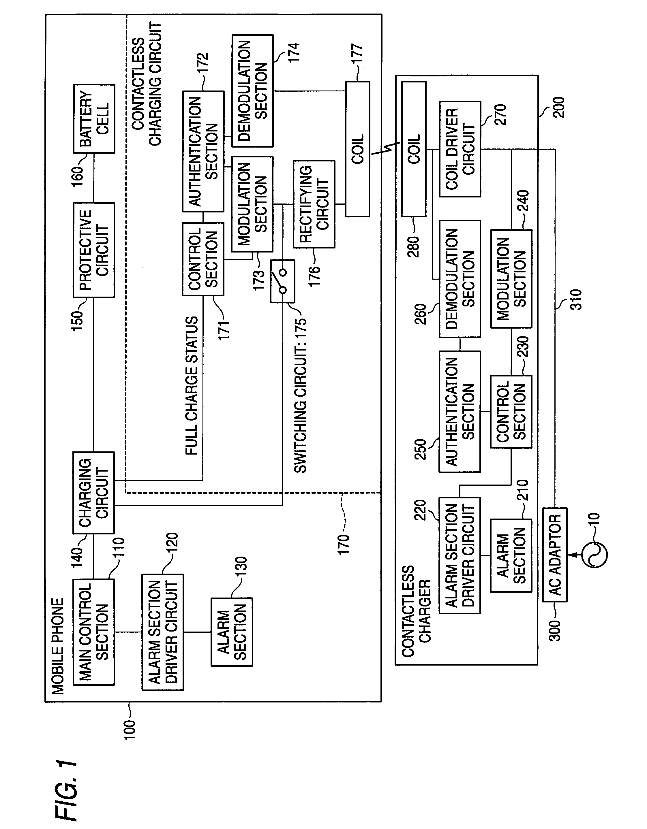
[0084]FIG. 1 is a block diagram for describing an overview of a contactless charging system of a first embodiment of the present invention. As shown in FIG. 1, the contactless charging system of the present embodiment is made up of a mobile phone 100, a contactless charger 200, and an AC adaptor 300. The mobile phone 100 is supplied with electric power while remaining out of contact with the contactless charger 200 and can recharge a battery cell (a secondary battery) 160 to be described later. Here, the term “contactless” means that the mobile phone 100 and the contactless charger 200 can exchange electric power (an electric wave), a signal, and the like, while they are not in direct, electrical conduction with each other by way of their metal terminals.

[0085]The mobile phone 100 has a main control section 110, an alarm section driver circuit 120, an alarm section 130, a charging circuit 140, a protective circuit 150, a battery cell 160, and a contactless charging circuit 170. The ...

second embodiment

[0134]FIG. 7 is a block diagram for describing an overview of a contactless charging system of a second embodiment of the present invention. As shown in FIG. 7, the present embodiment differs from the first embodiment in that the contactless charging circuit 170 is additionally provided with a voltage detection circuit 178 and a determination circuit 179. The voltage detection circuit 178 is connected to the protective circuit 150, and the determination circuit 179 is connected between the voltage detection circuit 178 and the control section 171.

[0135]In contrast with the first embodiment, in the case that the mobile phone 100 again needs recharging after completion of recharge, the contactless charging system is imparted with a function of restarting charge in the present embodiment. When the mobile phone 100 is left on the contactless charger 200 after having finished being recharged, there are cases where the voltage of the battery cell 160 decreases. Even in such a case, the co...

third embodiment

[0163]FIG. 14 is a block diagram for describing the overview of a contactless charging system of a third embodiment of the present invention. As shown in FIG. 14, in the present embodiment, the mobile phone 100 in the contactless charging system of the second embodiment is independently provided with a battery pack 400 including the coil 177, the protective circuit 150, and the battery cell 160. The battery pack 400 is configured so as to be removable from a main unit that is the other portion of the mobile phone 100 and independently tradable.

[0164]FIG. 15 is a modification of the contactless charging system shown in FIG. 14. As shown in FIG. 15, in the present embodiment the mobile phone 100 of the contactless charging system of the second embodiment is independently provided with the battery pack 400 that includes the overall contactless charging circuit 170, the protective circuit 150, and the battery cell 160. The battery pack 400 of the present embodiment includes the principa...


PUM


Abstract

To provide a contactless charging system that provides superior usability and allows for a reduction in power consumption and a safety measure, as well as to provide an electronic device, a contactless charger, and a battery pack for an electronic device which are used in the system.A contactless charging system is made up of a mobile phone 100 that is an electronic device and a contactless charger 200 that recharges the mobile phone 100 in a contactless manner. The mobile phone 100 transmits a full charge command indicating completion of charge. Upon receipt of the full charge command, the contactless charger 200 shifts to a charge stop state in which charge of the mobile phone 100 is not performed. In the charge stop state, the contactless charger 200 generates a load check signal for checking whether or not the mobile phone 100 is placed in the contactless charger 200 in a rechargeable state, and transmits the signal. Further, the contactless charger 200 also generates a charge restart check command for checking whether or not the mobile phone 100 requests recharge in a charge stop state, and transmits the command.

Description

TECHNICAL FIELD[0001]The present invention relates to a contactless charging system that recharges an electronic device with electric power supplied from a charger, the electronic device, a contactless charger, and a battery pack for the electronic device.BACKGROUND ART[0002]In order to assure a power source for a portable electronic device, such as a mobile phone, a secondary battery that enables performance of repetitive charge-discharge operations is used in the electronic device. A contactless charging system that enables recharging of the secondary battery without contacting the electronic device has been conceived as a system for recharging the secondary battery.[0003]Such a contactless charging system has become prevalent primarily among devices, charging terminals of which are desired to avoid exposure, such as an electric shaver. Future proliferation of the contactless charging system in a device, such as a mobile phone, is conceived. Patent Documents 1 and 2 describe; for ...

Claims


Application Information

Patent Timeline
IPC IPC(8): H02J7/00H02J7/04
CPCH01M10/44H02J7/025H01M10/448H01M10/446H02J50/10H02J50/80Y02E60/10H02J50/60
Inventor TAKAHASHI, HIROYUKIOKU, HIROYUKIOSHIMI, MASANORI
Owner PANASONIC INTELLECTUAL PROPERTY MANAGEMENT CO LTD
Learn More