
Pressure sensor

a technology of pressure sensor and sealing diaphragm, which is applied in the direction of fluid pressure measurement by mechanical elements, instruments, measurement devices, etc., can solve the problems of huge pressure changes, damage to pressure sensors, and possible damage to sealing diaphragms or micromechanical elements covered by sealing diaphragms, etc., and achieves the effect of cheap manufacturing

Active Publication Date: 2010-03-18
DANFOSS AS
View PDF11 Cites 9 Cited by
  • Summary
  • Abstract
  • Description
  • Claims
  • Application Information

AI Technical Summary

Benefits of technology

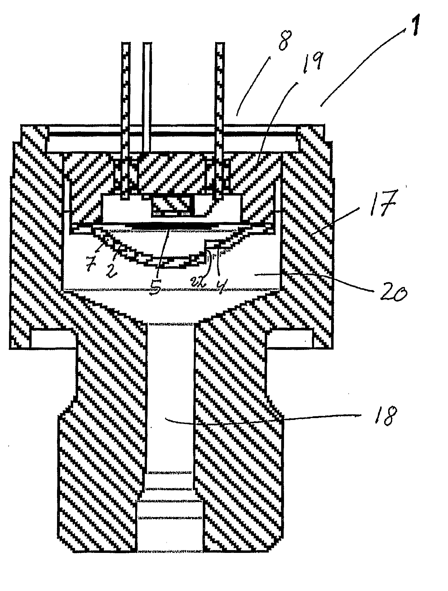
[0010]The object of this invention is to make a restriction element for a pressure sensor to protect the pressure element especially the sealing diaphragm from damaging pulses or other flow related damages. The restriction element is easy to place in the pressure sensor, it cannot fall out and disappear, and it is cheap to manufacture. The restriction element can be an integrated part of the pressure element, or it can be an independent part placed in the chamber between the inlet and the pressure element. The invention is a restriction element for a pressure sensor.
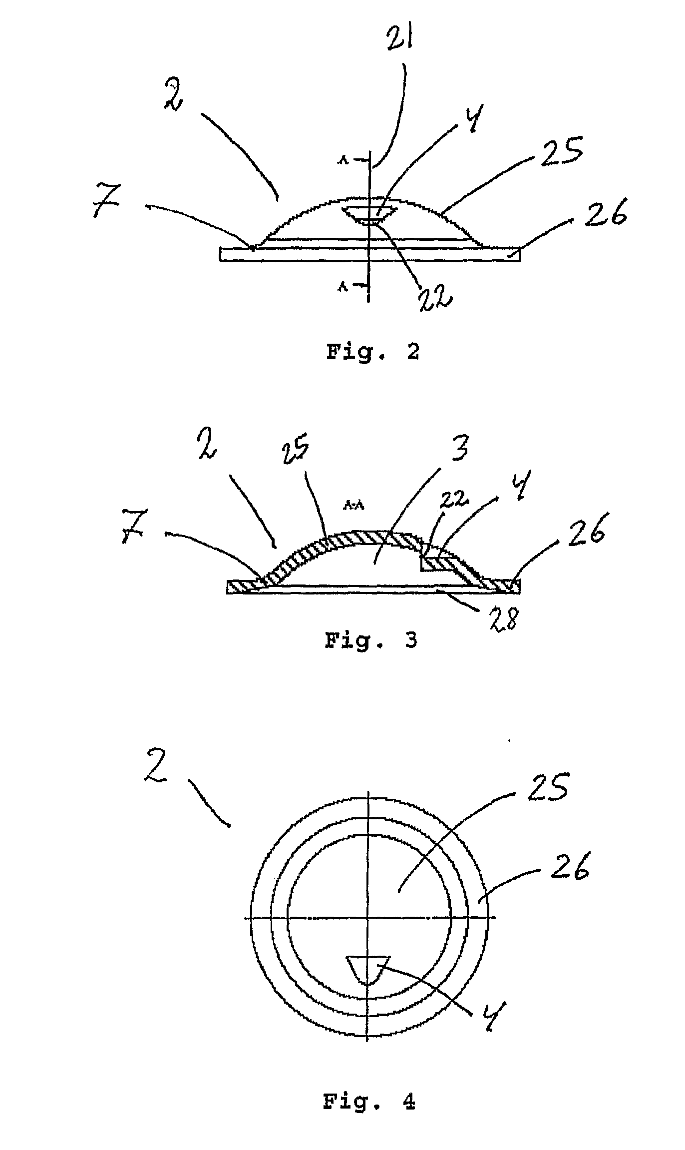
[0013]By using the restriction element integrated in the weld support element the restriction element is simple and cheap to manufacture, because the restriction element and the weld support element is merged in one unit and can be manufactured in one step. In the same manufacturing procedure a nozzle with a sufficient accurate small orifice opening can be made. This simplifies the production and reduces the cost compared to existing solutions. Since the restriction element is part of the weld support element; the restriction element is practically free of cost.
[0014]By placing the pulse snubbing restriction element between the fluid inlet channel and the pressure element, the restriction element is placed in a way it cannot fall out. Further more it makes it easier to assemble the pressure sensor, because the restriction element is welded to the pressure element and therefore mounting the pressure element and the restriction part is done in one operation.
[0022]When a flow system is empty and then filled with the flow medium, the start up jets occurs. The restriction element in this case shields the sealing diaphragm and prevents the jets to hit the sealing diaphragm directly.
[0023]The pressure peaks occurring in the system is not a real problem, when the measuring diaphragm is of silicon since silicon can handle higher pressure, the orifice opening in the nozzle can be relatively big so pressure peaks can pass into the damping chamber. However cavitations should preferable stay outside the damping chamber, so the nozzle prevents flow medium to flow out of the damping chamber when cavitations occurs, protecting the sealing diaphragm from the effects of flow medium returning to fill the cavitations. If a measuring diaphragm of steel or similar materials is used, the orifice opening in the nozzle can be smaller to damp the pressure peaks.

Problems solved by technology

The problems causing damage can be cavitations or pressure peaks or start up liquid jets.
In flow systems where sudden changes in the flow can occur for example by closing a valve, it is well known that cavitations related to “liquid hammer” can give huge pressure changes which can cause damage to pressure sensors especially to the sealing diaphragm.
When a valve suddenly is closed the flow medium decelerates, creating cavitations forming gas pockets and when the flow medium returns, it will result in huge pressure changes.
If these cavitations are close to a pressure sensor, the change in pressure will have the effect that liquid will be hammered against the sensor causing possible damage to the sealing diaphragm or to the micromechanical elements covered by the sealing diaphragm.
Pressure peaks, occurring in the flow system due to changes in the flow, can also damage the diaphragms in a pressure sensor.
This is however mostly a problem for the measuring diaphragm inside the pressure element.
The start up jets can damage the sealing diaphragm.
If the distance between the nozzle and the sealing diaphragm is shorter, there is a risk a damaging liquid-jet in the start-up situation will damage the sealing diaphragm.
Further more the existing solutions in form of pulse snubbing restriction elements are difficult to mount, because they are placed in the fluid inlet.
If the restriction element is damaged, it can fall out and disappear.

Method used


Image

  • Pressure sensor
  • Pressure sensor
  • Pressure sensor

Examples


Embodiment Construction

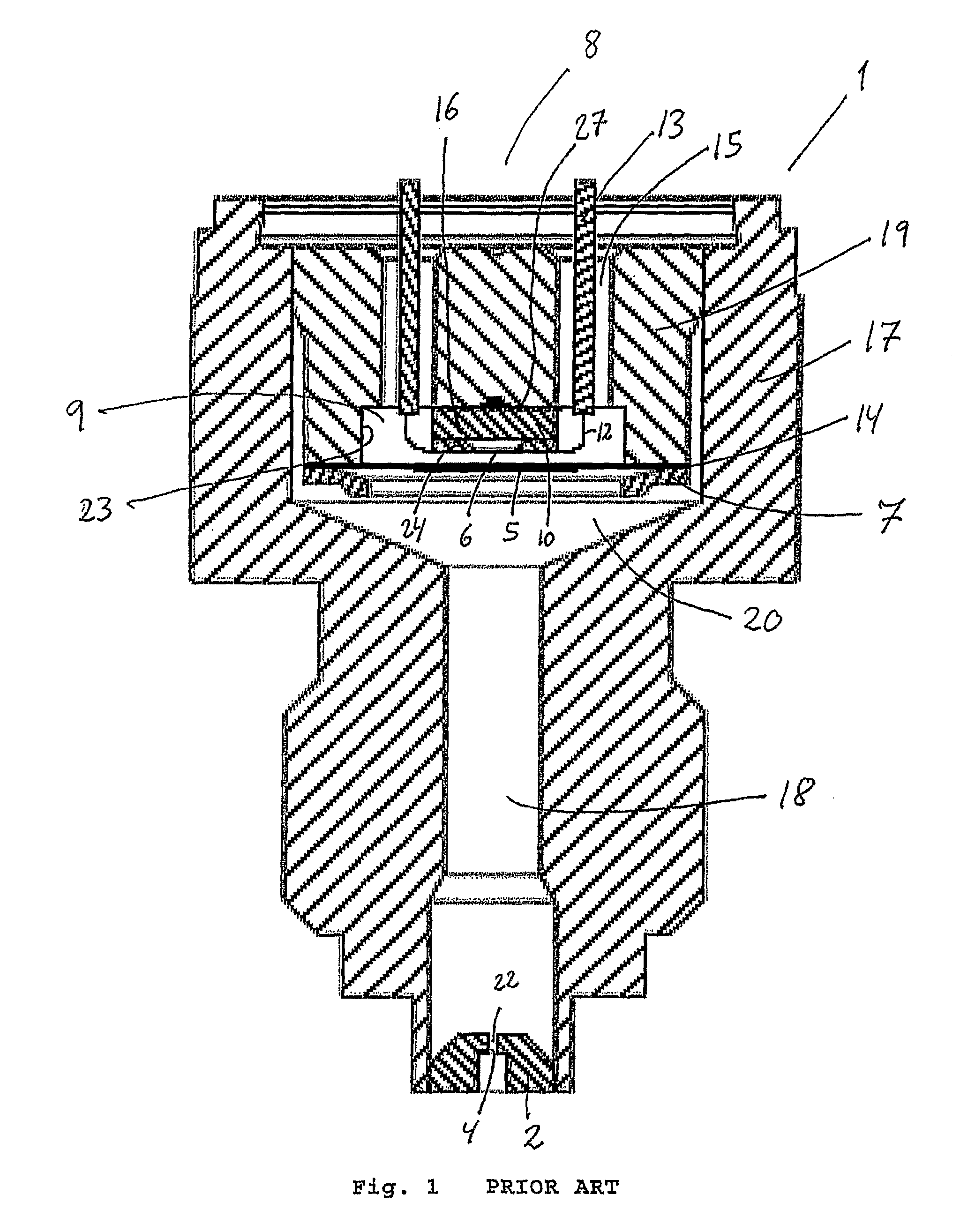
[0033]FIG. 1 is a prior art pressure sensor 1 comprising a housing 17 with a fluid inlet channel 18 and a chamber 20. In the chamber is mounted a pressure element 8. The Pressure element 8 comprises a housing part 19 with a sensor element 16 and a sealing diaphragm 5. The sealing diaphragm 5 covers a recess 23 forming a cavity 9. The sensor element 16, comprising a support 10 and a silicon (Si) sensor 24, is placed in the cavity 9 fastened to the housing part 19 by an adhesive 27. The Si-sensor 24 has measuring diaphragm 6. The Si-sensor is connected to bond wires 12 and feed-through pins 13. The feed through pins are isolated by an isolation layer 15. The sealing diaphragm 5 is placed between the housing part 19 and a weld support element 7. The weld support element 7 is used to support the sealing diaphragm 5 during welding, because the sealing diaphragm 5 is to thin to be welded without support, the welding leaves a weld joint 14. A restriction element 2 is placed in the inlet ch...


PUM


Abstract

The invention provides a restriction element for a pressure sensor to protect the pressure element from flow related damage. The pressure sensor comprising a housing with a fluid inlet channel and a chamber with a pressure element. The pressure element comprises a housing part with a recess covered by a sealing diaphragm forming a cavity. In the oil-filled cavity a sensor element is placed. The restriction element is placed in front of the sealing diaphragm protecting the pressure element and especially the sealing diaphragm from a damaging pulse or other flow related damages caused by sudden changes in a flow system for example by closing a valve.

Description

CROSS REFERENCE TO RELATED APPLICATIONS[0001]This application is entitled to the benefit of and incorporates by reference essential subject matter disclosed in International Patent Application No. PCT / DK2007 / 000513 filed on Nov. 21, 2007 and Danish Patent Application No. PA 2006 1526 filed Nov. 22, 2006.FIELD OF THE INVENTION[0002]The present invention relates to a pressure sensor comprising a housing with a fluid inlet channel and a chamber. In the chamber is placed a pressure element comprising a housing part with a recess. The recess is covered by a sealing diaphragm to provide a substantially closed cavity. In the cavity is placed a measuring diaphragm. A restriction element is placed in front of the sealing diaphragm to protect the sealing diaphragm from a damaging pulse or other flow related damages.BACKGROUND OF THE INVENTION[0003]In a flow system different problems caused by changes in the flow can damage a pressure sensor like the one in this invention; especially the seali...

Claims


Application Information

Patent Timeline
IPC IPC(8): G01L9/00
CPCG01L19/0038G01L19/0645G01L19/0609
Inventor VOGLER, JES
Owner DANFOSS AS
Learn More