
Piezoelectric acoustic transducer

a technology of piezoelectric and acoustic transducer, which is applied in the direction of electrical transducers, deaf-aid sets, transducer details, etc., can solve the problems of piezoelectric loudspeakers with danger of short-circuiting, difficulty in reducing the thickness of loudspeakers, and deterioration of low-frequency sound pressure, etc., to achieve flattening of sound pressure characteristics, low pitch sound, and easy vibration

Active Publication Date: 2010-03-11
PANASONIC CORP
View PDF7 Cites 8 Cited by
  • Summary
  • Abstract
  • Description
  • Claims
  • Application Information

AI Technical Summary

Benefits of technology

[0033]According to the present invention described above, a resistance, which is connected in series with a piezoelectric element and which has a property of a capacitor, is integrally formed to one part of an electrode formed on a diaphragm surface by using a printing technology and the like. By this, it is possible to flatten a sound pressure characteristic without increasing the number of parts, and in addition, attain space-saving. Furthermore, according to the present invention, supporting a vibrating section with a supporting section allows the vibrating section to vibrate easily at low frequency. By this, it is possible to play a low pitch sound with high sound quality. As a result, according to the present invention, a piezoelectric type loudspeaker, which achieves both space-saving and high sound quality without increasing the number of parts, can be provided.

Problems solved by technology

However, when the electrodynamic type is used, due to the structure thereof, it is inherently difficult to reduce the thickness of a loudspeaker; and when reduction in thickness is attempted, there are problems such as: deterioration of low-frequency sound pressure, necessity for measures to prevent magnetic leak due to the use of a magnetic circuit, and the like.
For this reason, the piezoelectric type loudspeaker has a danger of short-circuiting due to an overcurrent at a high frequency range.
Furthermore, the piezoelectric type loudspeaker causes performance deterioration of the piezoelectric material due to reduction in the capacitance by a pyroelectric effect, when used at a condition where temperature shifts extensively.

Method used


Image

  • Piezoelectric acoustic transducer
  • Piezoelectric acoustic transducer
  • Piezoelectric acoustic transducer

Examples


first embodiment

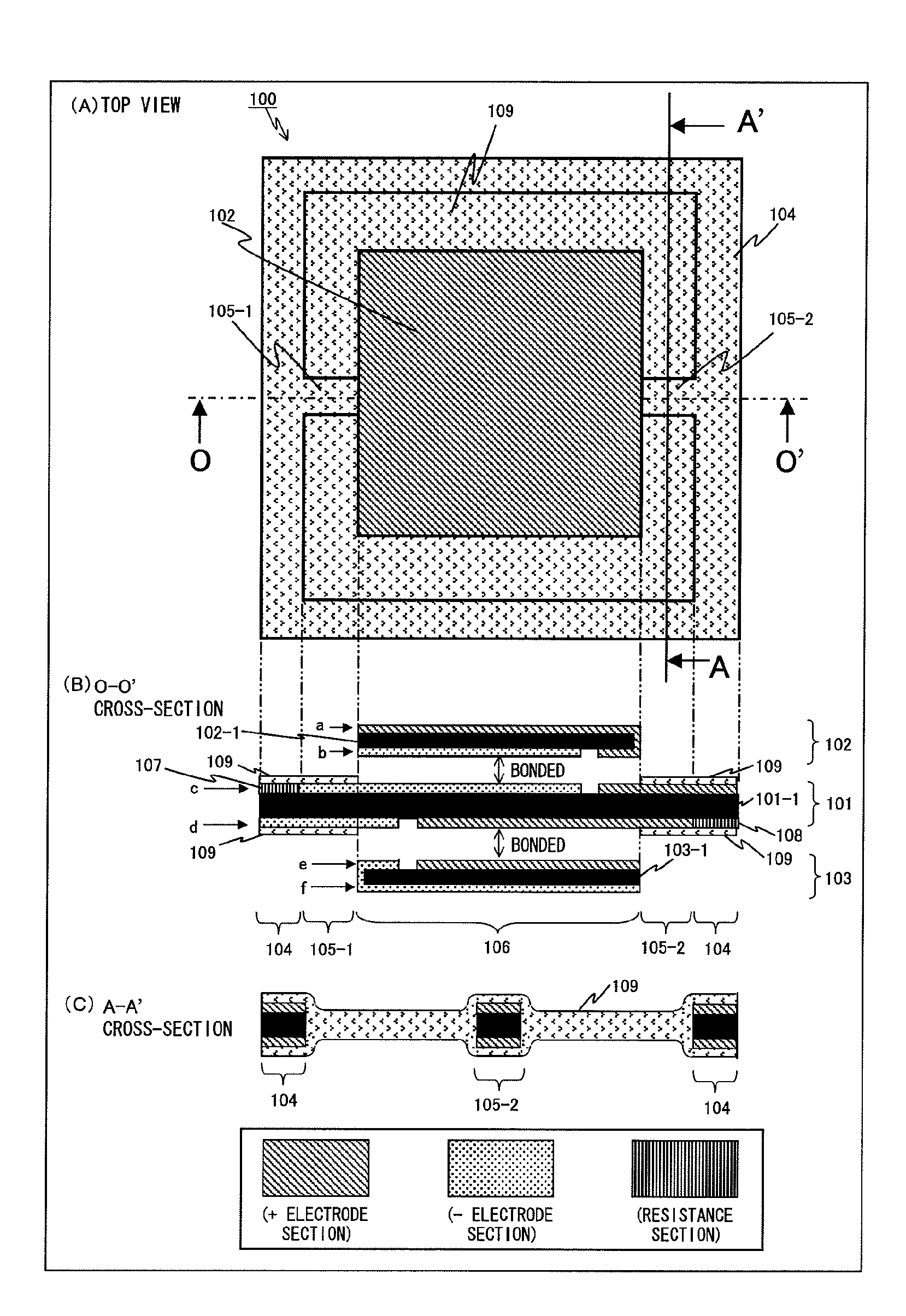
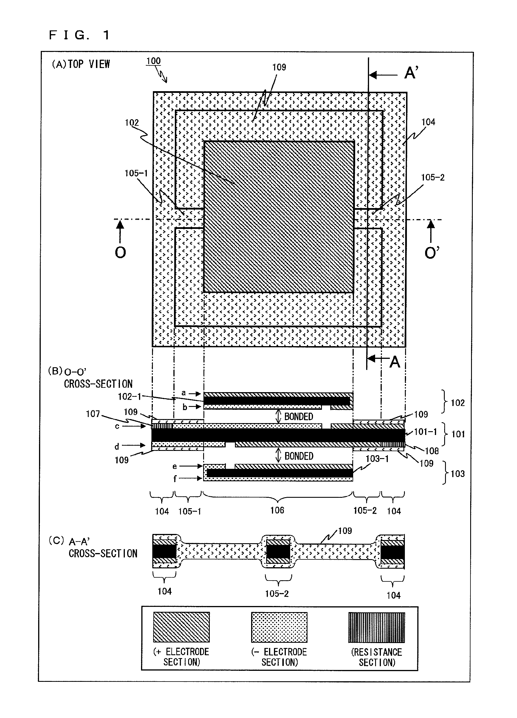
[0084]FIG. 1 is a top view and cross sectional views of one example of a piezoelectric type loudspeaker 100 according to a first embodiment. In FIG. 1, (A) is the top view, (B) is a cross-sectional view of O-O′, and (C) is a cross-sectional view of A-A′. As shown in (A) to (C) of FIG. 1, the piezoelectric type loudspeaker 100 includes a diaphragm 101, a piezoelectric element 102, a piezoelectric element 103, and a filler 109. In (B) of FIG. 1, the diaphragm 101, the piezoelectric element 102, and the piezoelectric element 103 are illustrated separately for convenience of description; however, in practice, the diaphragm 101, the piezoelectric element 102, and the piezoelectric element 103 are bonded to each other.

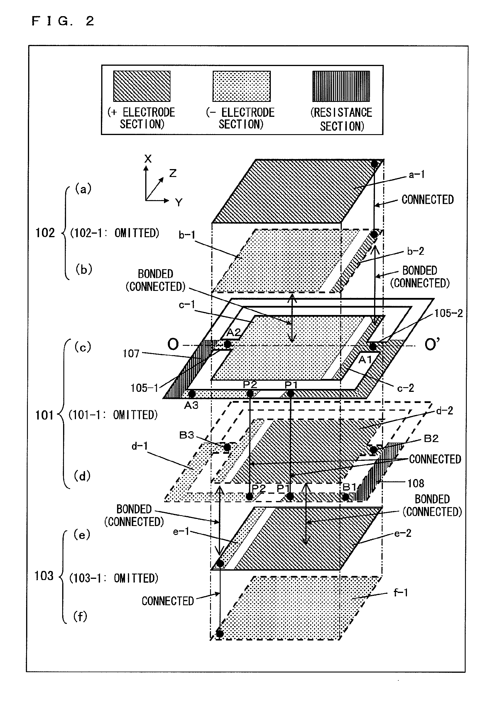
[0085]The piezoelectric element 102 includes: a piezoelectric material 102-1; an electrode layer a which is formed on the upper surface of the piezoelectric material 102-1; and an electrode layer b which is formed on the lower surface of the piezoelectric material 102-1 (ref...

second embodiment

[0100]In addition to the characteristics of the piezoelectric type loudspeaker 100 according to the first embodiment, a piezoelectric type loudspeaker 200 according to a second embodiment has a characteristic in which an electrode of a piezoelectric element is split plurally, and an electrode connected to a resistance in series and an electrode not connected to a resistance are provided. Description centered on this characteristic is given in the following, and descriptions of characteristics in common with the piezoelectric type loudspeaker 100 according to the first embodiment are omitted in principle.

[0101]FIG. 4 is a top view and cross sectional views of one example of the piezoelectric type loudspeaker 200 according to the second embodiment. In FIG. 1, (A) is a top view, (B) is a cross-sectional view of O1-O1′, (C) is a cross-sectional view of O2-O2′, and (D) is a cross-sectional view of O3-O3′. As shown in (A) to (D) of FIG. 4, the piezoelectric type loudspeaker 200 includes: ...

third embodiment

[0115]In addition to the characteristics of the piezoelectric type loudspeaker 100 according to the first embodiment, a piezoelectric type loudspeaker 300 according to a third embodiment has a characteristic in which an electrode of a piezoelectric element is split plurally, and a reverse voltage is given to one part of the electrode. Description centered on this characteristic is given in the following, and descriptions of characteristics in common with the piezoelectric type loudspeaker 100 according to the first embodiment are omitted in principle. As a footnote, descriptions with reference to a top view and a cross sectional view of the piezoelectric type loudspeaker 300 are omitted for the third embodiment. Additionally, description of the configuration of the lower surface side of the diaphragm is omitted in the following.

[0116]FIG. 7 is a diagrammatic perspective view for describing each electrode layer that constructs the piezoelectric type loudspeaker 300 according to the t...


PUM


Abstract

A piezoelectric type loudspeaker, which achieves both space-saving and high sound quality without increasing the number of parts, is provided. In order to achieve this, the present invention includes: a piezoelectric element constructed of a piezoelectric material interposed between two surface electrodes; and a diaphragm of which at least one principal surface is provided with a print wiring and at least one principal surface is bonded to the piezoelectric element, and the diaphragm includes: a frame section; a vibrating section which is bonded with the piezoelectric element, and which vibrates; and at least one supporting section which connects the frame section and the vibrating section, and which supports the vibrating section, and either the frame section or the at least one supporting section includes at least one electrical resistance which is integrally formed to the print wiring, and which constructs, in combination with the piezoelectric element, a series-RC circuit.

Description

TECHNICAL FIELD[0001]The present invention relates to a piezoelectric acoustic transducer, and more specifically, relates to a piezoelectric acoustic transducer that achieves both space-saving and high sound quality.BACKGROUND ART[0002]In recent years, the trend toward thinner and smaller mobile phones and other mobile instruments has been accelerating; and in addition, the need for thinner and smaller parts mounted in audio-visual instruments and the like has also been increasing.[0003]As a method for driving a loudspeaker that plays a ring tone or a music signal with a mobile phone and the like, an electrodynamic type has been used conventionally. However, when the electrodynamic type is used, due to the structure thereof, it is inherently difficult to reduce the thickness of a loudspeaker; and when reduction in thickness is attempted, there are problems such as: deterioration of low-frequency sound pressure, necessity for measures to prevent magnetic leak due to the use of a magn...

Claims


Application Information

Patent Timeline
IPC IPC(8): H04R17/00
CPCH04R1/2876H04R31/006H04R17/00H04R3/04
Inventor FUJISE, AKIKOMATSUMURA, TOSHIYUKISATOH, KAZUE
Owner PANASONIC CORP
Learn More