Motor control system

a technology of motor control and control system, which is applied in the direction of electric controllers, ignition automatic control, instruments, etc., can solve the problems of insufficient shortening the positioning settling time ts, inability to improve more, and inability to reduce so as to suppress the vibration of the machine base, and suppress the effect of the vibration

Active Publication Date: 2010-03-11
SANYO DENKI CO LTD
View PDF24 Cites 15 Cited by
  • Summary
  • Abstract
  • Description
  • Claims
  • Application Information

AI Technical Summary

Benefits of technology

[0018]According to the present invention, gains for the first feedback section and the second feedback section are adjustable with gains for the model position controller and the model speed controller and a parameter value for the torque command low-pass filter in the feedback control system set to arbitrary values in the physically settable range, suppressing vibration of the machine base. According to the present invention, it is thus possible to suppress vibration of a machine base and achieve high-speed positioning without using a special sensor but using a model control system.
[0019]Preferably, the first feedback section may be configured to generate the first feedback command which contains model machine base speed information and model machine base acceleration information on the machine base in addition to the model machine base position information. Compared to when only the model machine base position information is fed back, a model speed loop gain may readily be used as a generally usable value.
[0020]In implementing the present invention, the gain set for the model position controller and the gain set for the model speed controller are set to be the same as the gain set for the position controller and the gain set for the speed controller, respectively. In addition, the first feedback gain set for the first feedback section and the second feedback gain set for the second feedback section are set to suppress vibration of the machine base.
[0021]A plurality of parameters in the model control system are set such that the characteristic equations in the state equations of the model control system have a quintuple root and that the feedback control system is stabilized. If the plurality of parameters are determined in this way, vibration may be suppressed and high-speed positioning may be achieved.
[0022]According to the present invention, gains (parameters) for the first feedback section and the second feedback section are adjustable with gains for the model position controller and the model speed controller and a parameter value for the torque command low-pass filter in the feedback control system set to arbitrary values in the physically settable range, thereby suppressing vibration of the machine base and achieving high-speed positioning.

Problems solved by technology

The disturbance suppression characteristics are restricted by high-frequency resonance of the mechanical system etc., and therefore cannot be improved more than a certain level.
However, actual mechanical systems have portions with a lower rigidity which cause vibration.
If the motor is driven to drive the table at a high speed, the machine base sways because of the rigidity of the leveling bolts, causing vibration of the machine base.
However, as can be seen from FIG. 6B, a positioning settling time Ts cannot be sufficiently shortened because of a delay caused by the prefilter.
As a result, even if vibration is suppressed by feeding back the torsion angle and the torsion angle speed, for example, the vibration suppression effect may be impaired if the parameter for the pseudo-adaptive speed controller 15 is changed to restrict the simulated speed deviation.
It is thus questionable whether or not vibration of a machine base is really suppressed by the technique disclosed in JP2002-163006A, since it does not clarify a machine model.
Therefore, a thrust command in the feedback control system may not match the thrust command in the model control system because of the configuration of a converter or a delay caused by a converter, even if there is no error between the model control system and the feedback control system.
Consequently, sufficient model following control characteristics may not be obtained.
Moreover, JP2004-21413A does not clarify how the parameters are to be set in order to suppress vibration.
Therefore, it may be not be possible to both suppress vibration and achieve high-speed positioning.
However, the gain for the speed controller in the feedback control system is restricted in terms of an upper limit by the rigidity of the mechanical system etc., and thus cannot be set to a significantly large value.
Thus, even if the state feedback theory is applied to the model control system of FIG. 8 to calculate such parameter values that are expected to suppress vibration and achieve high-speed positioning, vibration may still be caused, making it difficult to control the motor using the calculation results.
However, the sensor may reduce the reliability of the method in case of a failure, and may also increase the cost.

Method used


Image

  • Motor control system
  • Motor control system
  • Motor control system

Examples


Embodiment Construction

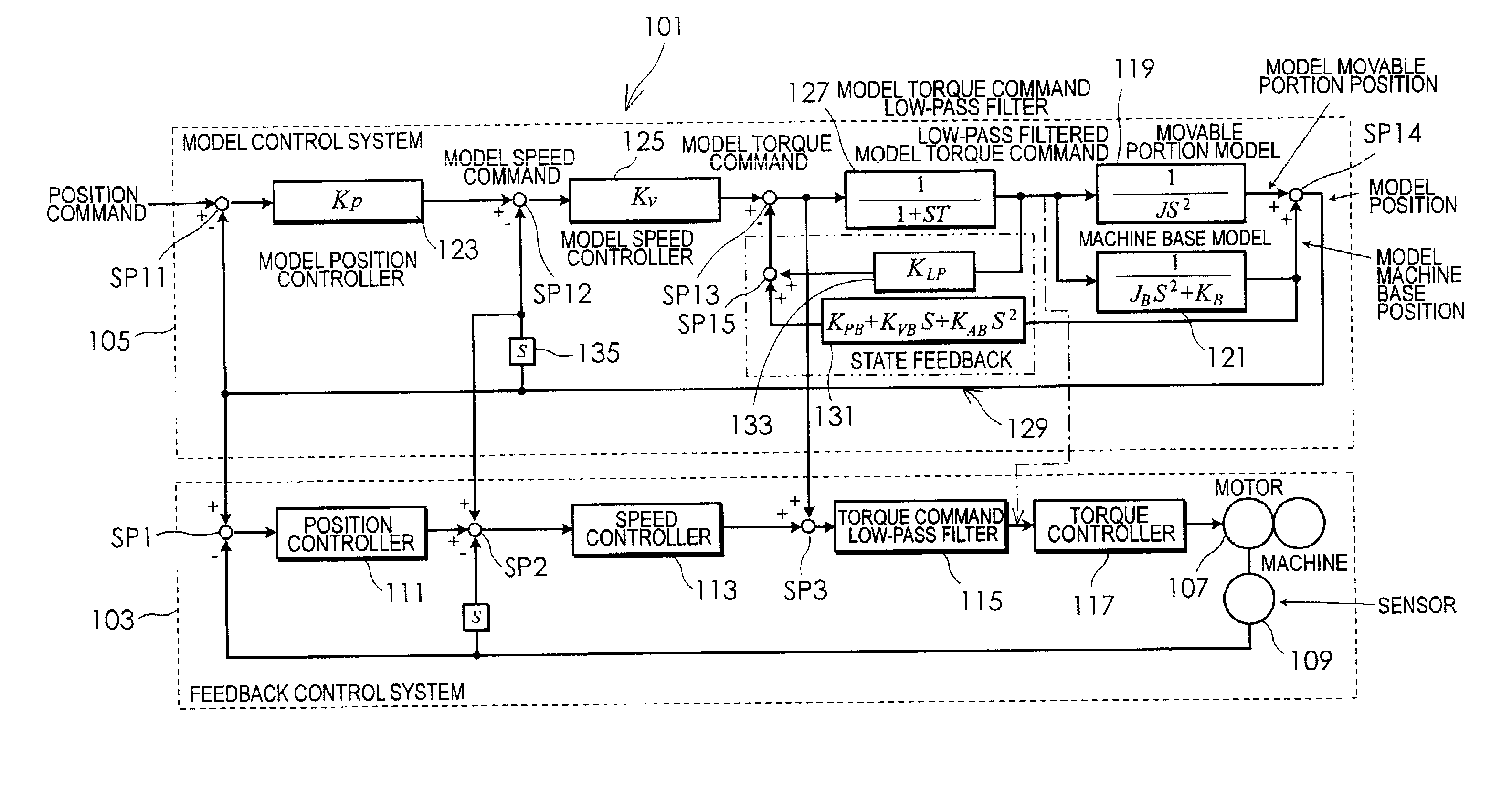
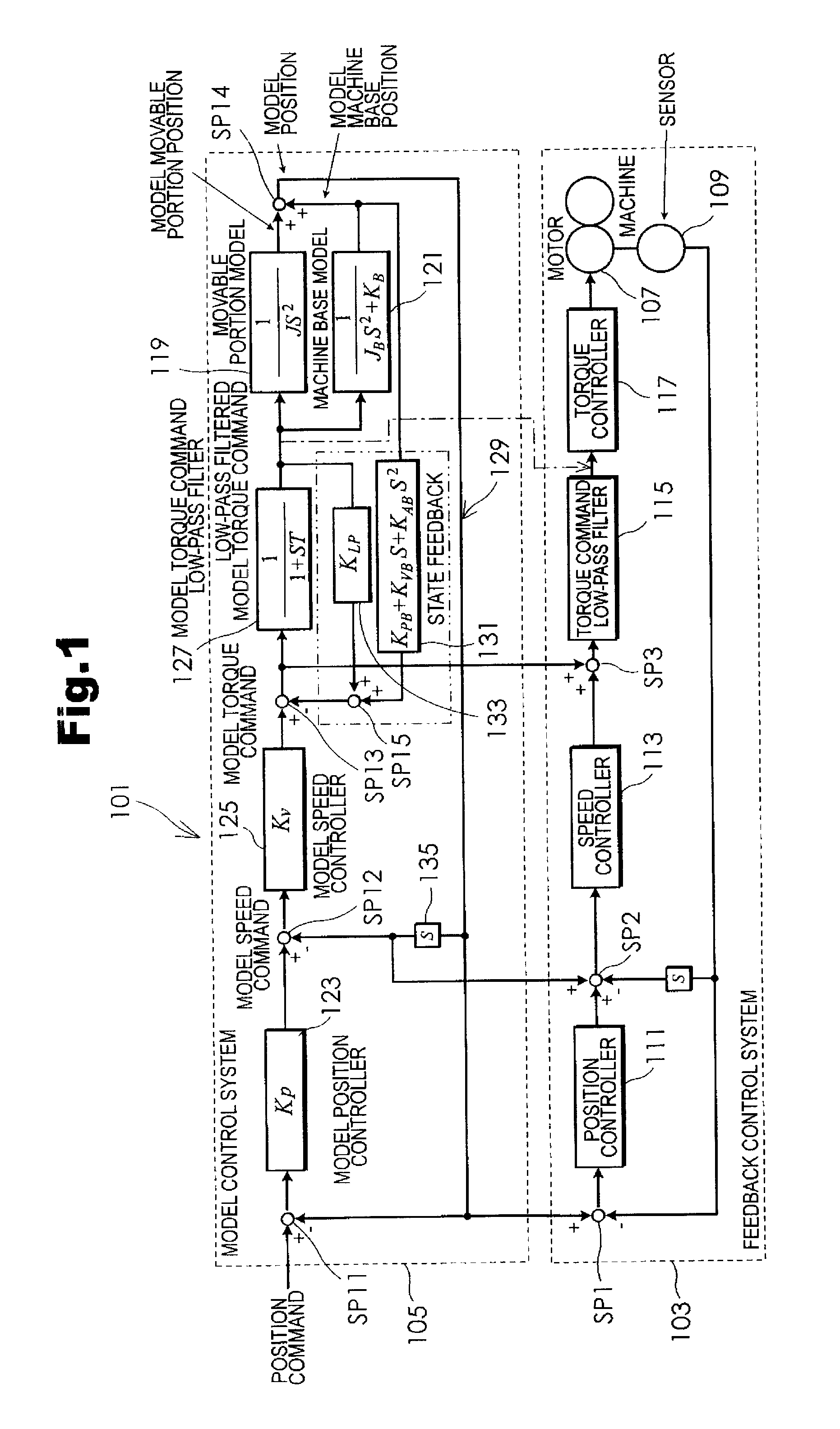
[0040]Hereinafter, an embodiment of the present invention will be described in detail with reference to the drawings. FIG. 1 is a block diagram showing the configuration of a motor control system according to the present invention. A motor control system 101 of the embodiment comprises a feedback control system 103 and a model control system 105. The feedback control system 103 includes a position sensor 109 that detects the rotational position of a shaft of a motor 107 and that is constituted by an encoder, a position controller 111, a speed controller 113, a torque command low-pass filter 115, and a torque controller 117. An output (position information) of the position sensor 109 is fed back to the position controller 111. Also, the output (position information) of the position sensor 109 is differentiated and fed back to the speed controller 113 as speed information. The position controller 111 receives the differential between the position information detected by the position s...


PUM


Abstract

A motor control system suppresses vibration of a machine base and achieves high-speed positioning without using a special sensor but using a model control system. A first feedback section outputs a first feedback command generated based on model machine base position information and containing at least position information on the machine base. A second feedback section outputs a second feedback command containing a filtered model torque command. A differential between the sum of the first feedback command and the second feedback command obtained by a second addition section and the model torque command is calculated to give the differential to an input portion of a model torque command low-pass filter and an input portion of a torque command low-pass filter. The model control system gives a model position command to a position controller as a position command, and model machine base position information generated based on the model position command is added to a speed command input from the position controller to a speed controller.

Description

BACKGROUND OF THE INVENTION[0001]1. Field of the Invention[0002]The present invention relates to a motor control system that includes a model control system and performs model following control.[0003]2. Description of the Related Art[0004]Model following control is known as a technique for high-speed positioning of a machine such as a chip mounter using a motor control system. In the model following control, a model control system simulating an actual feedback control system is built up. The feedback control system is driven to follow the model control system. FIG. 2 shows the configuration of a motor control system adopting conventional model following control disclosed in Japanese Patent Application Publication No. 62-217304 (JP62-217304A). In the control system, the deviation between a position command and a model position is acquired and supplied to a model position controller to obtain a model speed command. A deviation between the model speed command and a model speed is then ...

Claims


Application Information

Patent Timeline
Patent Type & Authority Applications(United States)
IPC IPC(8): G05B5/01G05B13/04G05D3/12H02P29/00
CPCH02P6/001H02P23/04H02P6/10H02P2203/05H02P6/34
Inventor IDE, YUJI
Owner SANYO DENKI CO LTD
Why Eureka
Try Eureka