
Pool cleaner baseplate with inlet extension members and recessed wheels

a technology of pool cleaners and base plates, which is applied in the direction of gymnasiums, buildings, construction, etc., can solve the problems of reducing cleaning efficiency, prolonging cleaning time, and wasting externally provided electricity or power, so as to promote the laminar flow of incoming water, reduce turbulence, and ensure long-term attachment.

Active Publication Date: 2010-03-11
AQUATRON ROBOTIC TECH
View PDF3 Cites 41 Cited by
  • Summary
  • Abstract
  • Description
  • Claims
  • Application Information

AI Technical Summary

Benefits of technology

[0014]Since the user of the pool cleaner will preferably have the option of inserting and removing inlet extension members in order to determine which depth provides the best solution to the pre-existing surface conditions, including the particular type of pool surface, the existence of obstacles and extreme changes in contour, the ability to interchangeably insert and remove the extension members is a significant advantage of the invention.
[0015]In another embodiment, a baseplate formed by molding a polymeric composition is integrally formed with depending inlet extension members of predetermined depth. Interchangeable baseplates having integrally molded extension members of various depths can be inventoried and made available to purchasers for use with pools having known surface obstructions or conditions.
[0016]As will also be apparent to one of ordinary skill in the art, the extension members can be sold in kit form for installation using flush mounting means of attachment, including various types of adhesives and mechanical fasteners, e.g., threaded screws. For example, inlet extension members of the same, or approximately the same interior configuration as the inlet opening, can be provided with a mounting tape having release paper that is removed by the user to enable the extension member to be pressed into position around the inlet opening on the external surface of the baseplate. Although this type of mounting tape, when properly selected for the conditions in the pool, can provide a reliable long-term means of attachment, the use of mounting tape also permits the extension member to be removed, e.g., by the insertion of a knife blade or application of a liquid solvent to separate the extension member from its attachment to the baseplate. By using appropriate solvents and / or scraping tools, any remaining adhesive material can be removed from the baseplate and an inlet extension member of the different depth installed.
[0017]In yet another embodiment, the kit can include a number of inlet extension members corresponding in size and number to the inlets in the baseplate, where each inlet member is formed from a plurality of stackable, snap-fit or otherwise interlocking members that permit the user to vary the depth by changing the number of stackable elements. In a particularly preferred embodiment of this aspect of the invention, the lowermost element is configured to provide a rim surface that will promote laminar flow of the incoming water and minimize turbulence to thereby achieve the optimum efficiency in the flow pattern into the inlet opening. Mounting of the stackable elements can be by use of adhesive means or interlocking brackets that engage the baseplate in accordance with the structures described above for the unitary elements.
[0018]In yet another embodiment, an extension member is of adjustable depth and constructed of, e.g., close-fitting, interlocking telescoping tubular sections that permit the user to adjust the depth to suit the conditions present in the pool. A wide variety of adjustable constructions are known to those of ordinary skill in the art, as will be their adaptation to the use described above. Set screws and the like can be utilized to maintain one or more telescoping segments in a fixed, but variably adjustable position.
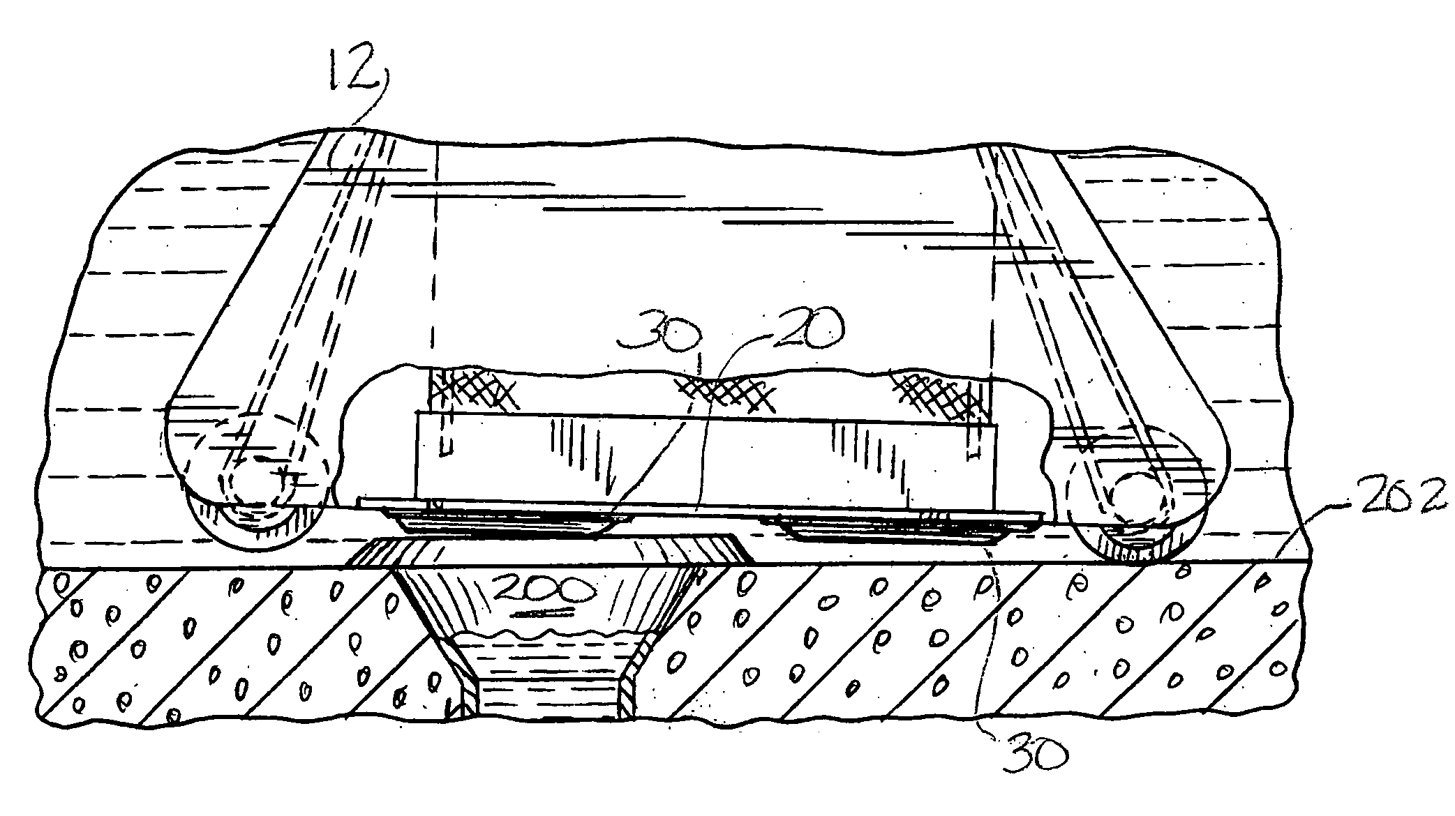
[0019]As will be understood from the earlier description, extending the suction point below the baseplate can increase the potential for contact with obstacles projecting from the surface being cleaned or engagement with extreme surface contours. In order to obviate this problem, in a further preferred embodiment, the baseplate includes at least one wheel mounted for rotation in a recess positioned adjacent the inlet opening extension member. In an especially preferred embodiment the wheel is displaced inwardly from the lateral edges of the baseplate.

Problems solved by technology

These obstacles can stop a robotic cleaner or delay the apparatus with much of the directional cycle spent with the apparatus immobilized or diverted from its intended path by a projecting obstacle or pool surface contour.
In either case, this is an undesirable result because it lengthens the cleaning time and wastes externally provided electricity or the power of an on-board battery.
Furthermore, the obstacle or contour can change the route of patterned travel of the apparatus, thereby reducing cleaning efficiency.
The obvious drawback is that the regular pattern of travel is changed thereby potentially reducing the efficiency of the cleaning apparatus.
Since the suction force diminishes rapidly with an increase in distance between the surface being cleaned and the baseplate inlet openings, merely raising the baseplate is not a practical solution to the problem of obstacles that project from the bottom or sidewall of the pool.

Method used


Image

  • Pool cleaner baseplate with inlet extension members and recessed wheels
  • Pool cleaner baseplate with inlet extension members and recessed wheels
  • Pool cleaner baseplate with inlet extension members and recessed wheels

Examples


Embodiment Construction

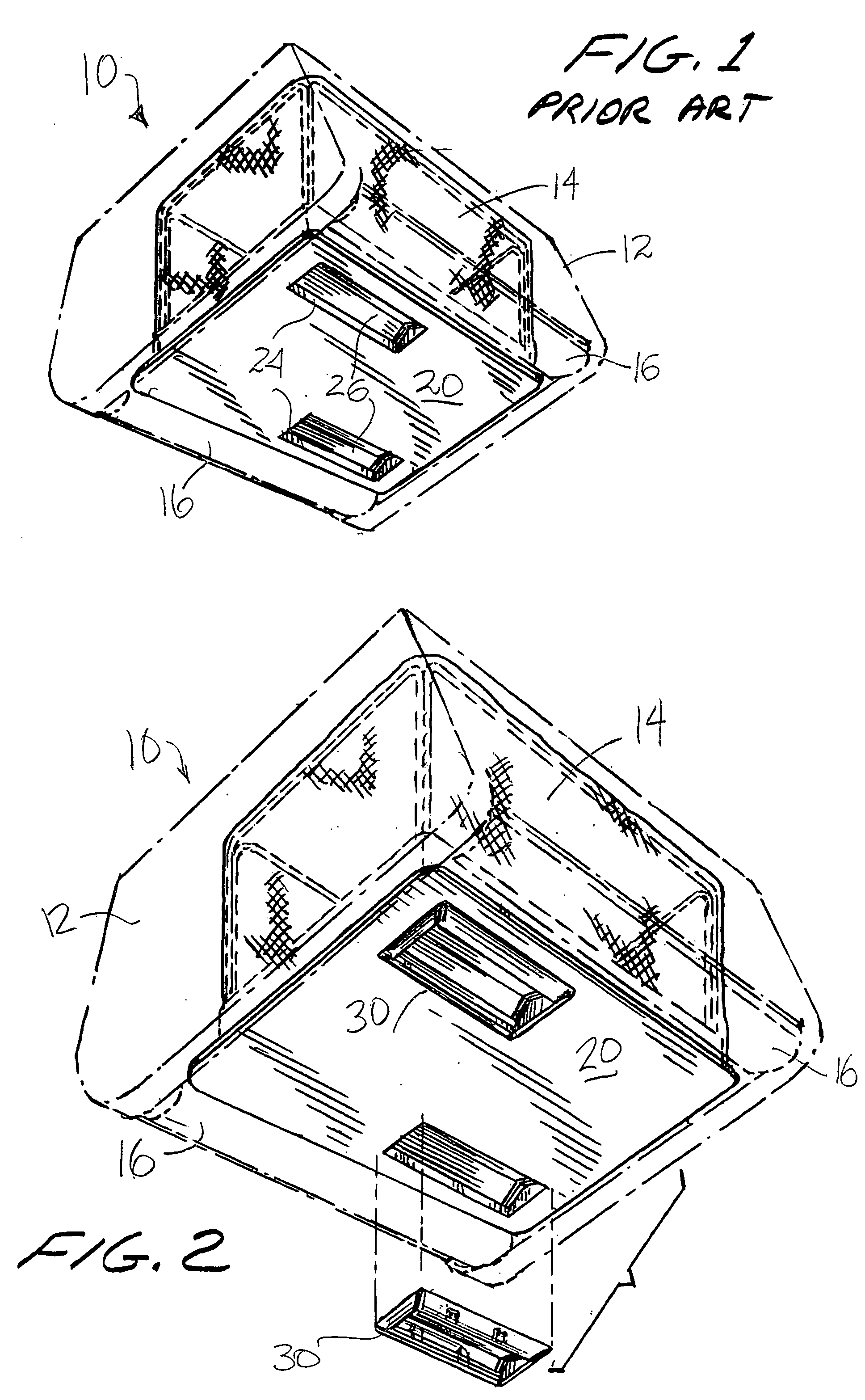
[0034]Referring to FIG. 1, a representative self-propelled robotic pool cleaner 10 of the prior art has an exterior housing 12, an internal filter assembly 14, transverse power driven rollers 16 and a baseplate 20 is schematically depicted. Baseplate 20 is attached to the bottom of the housing 12 and, as illustrated, has two inlet openings 24 that are closed by a pair of biased doors 26 that close when the water flow to the filter is stopped.

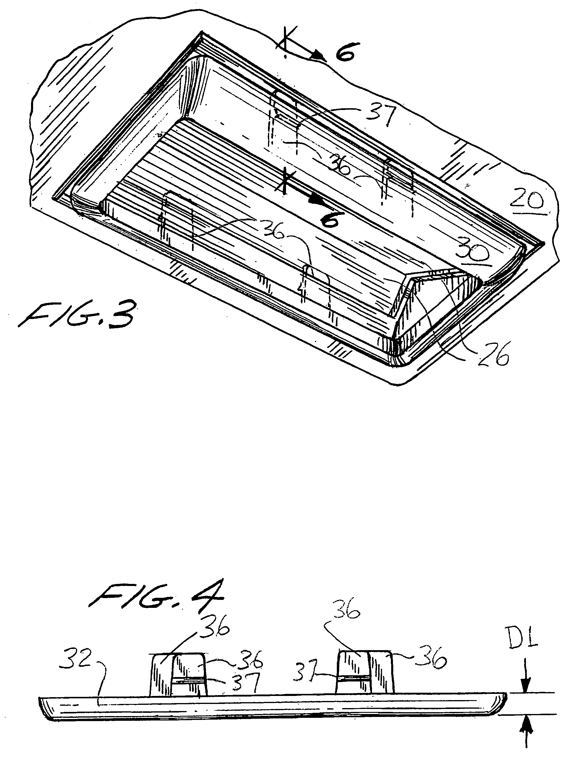
[0035]Referring now to FIG. 2, the baseplate 20 has been fitted with an inlet extension member, referred to generally as 30, that is assembled in a snap-fitting relation; a second inlet extension member is shown in position for attachment to the baseplate. As most clearly shown in FIGS. 3, 4 and 5, the inlet extension member 30 is formed with a plurality of upwardly projecting clips 36 that are semi-flexible and provided with projecting ridges 37 that engage the baseplate.

[0036]FIGS. 4 and 5 are side views of two inlet extension members 32, 34 o...


PUM


Abstract

A baseplate for a robotic self-propelled pool cleaner having one or more inlet openings through which water-borne debris passes prior to filtration is provided with downwardly depending inlet extension members having walls that define an opening corresponding in shape to the baseplate inlet opening and that are mounted in close-fitting relation to extend the water intake opening towards, but without touching, the pool surface to increase the suction force at the surface. The baseplate optionally includes a rotatable wheel mounted in an inboard recess in the baseplate on, or adjacent to the longitudinal centerline of the cleaner to facilitate passage over obstacles that would immobilize the pool cleaner by contact with an inlet extension member.

Description

FIELD OF INVENTION[0001]This invention relates to robotic self-propelled submersible pool and tank cleaners.BACKGROUND OF THE INVENTION[0002]Automated or robotic swimming pool cleaners traditionally contact and move about on the pool bottom and wall surfaces being cleaned on four axle-mounted wheels, resilient rollers that are transversely mounted at either end of the unit, or on endless tracks that are powered by a separate drive motor through a gear train to propel the robot over the surfaces of the pool that are to be cleaned. The water pump can drive a water turbine connected via a gear train to the wheels or endless track. Robotic swimming pool cleaners have a pump motor that powers a water pump that draws water through the moving unit and the moving water dislodges and / or “vacuums” debris up into a filter. The water pump can be internal or external to the robotic cleaner. The water exiting the unit having an internal pump in the form of a pressurized stream, or water jet can a...

Claims


Application Information

Patent Timeline
IPC IPC(8): E04H4/16
CPCE04H4/1654
Inventor ERLICH, GIORA
Owner AQUATRON ROBOTIC TECH
Learn More