Wind Turbine For Facilitating Laminar Flow

a technology of wind turbines and laminar flow, which is applied in the direction of magnetic bodies, magnetic circuit shapes/forms/constructions, greenhouse gas reduction, etc., can solve the problems of not incorporating the fixed geometries and controlled operating environment of current inventive subject matter, and achieve the effect of facilitating laminar flow

Active Publication Date: 2014-12-04
MAGNELAN TECH INC
View PDF5 Cites 5 Cited by
  • Summary
  • Abstract
  • Description
  • Claims
  • Application Information

AI Technical Summary

Benefits of technology

[0013]In most contemplated embodiments, the foils are circumferentially distributed about the axis using one or more laminar flow vanes As the foils rotate about the axis, each of the foils is a leading foil relative to the foil trailing immediately behind it, and is also a trailing foil relative to the foil immediately in front of it. Each of the foils has a leading edge at a specified distance (R1 for first foil, R2 for second foil . . . Rn for nth foil) from the axis. R2-Rn are each preferably within 20% of R1, and more preferably within 10% of R1. Additionally, each foil of a turbine has a chord (C1 for first foil, C2 for second foil . . . Cn for nth foil). C2-Cn are each preferably within 20% of C1, and more preferably within 10% of C1. Additionally or alternatively, each foil can advantageously be designed to fly in a circular path because it is largely non-planar on the high pressure side of the foil. Viewed from another perspective, each foil can have a high pressure portion that is entirely or substantially curved (i.e., along at least 90% of the high pressure portion) in a manner that facilitates laminar flow.

Problems solved by technology

It should be noted that while some catamarans now incorporate solid adjustable foils that attempt to stay within a created laminar flow environment, they do not incorporate the fixed geometries and controlled operating environment of the current inventive subject matter.

Method used


Image

  • Wind Turbine For Facilitating Laminar Flow
  • Wind Turbine For Facilitating Laminar Flow
  • Wind Turbine For Facilitating Laminar Flow

Examples


Embodiment Construction

[0021]The following description includes information that may be useful in understanding the present invention. It is not an admission that any of the information provided herein is prior art or relevant to the presently claimed invention, or that any publication specifically or implicitly referenced is prior art.

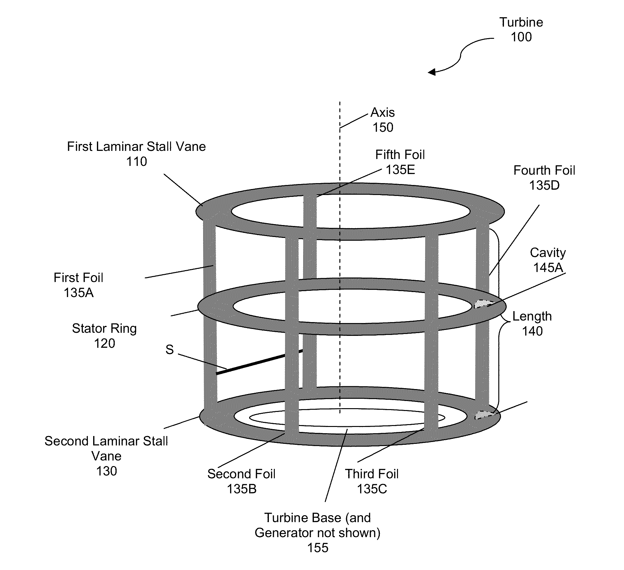
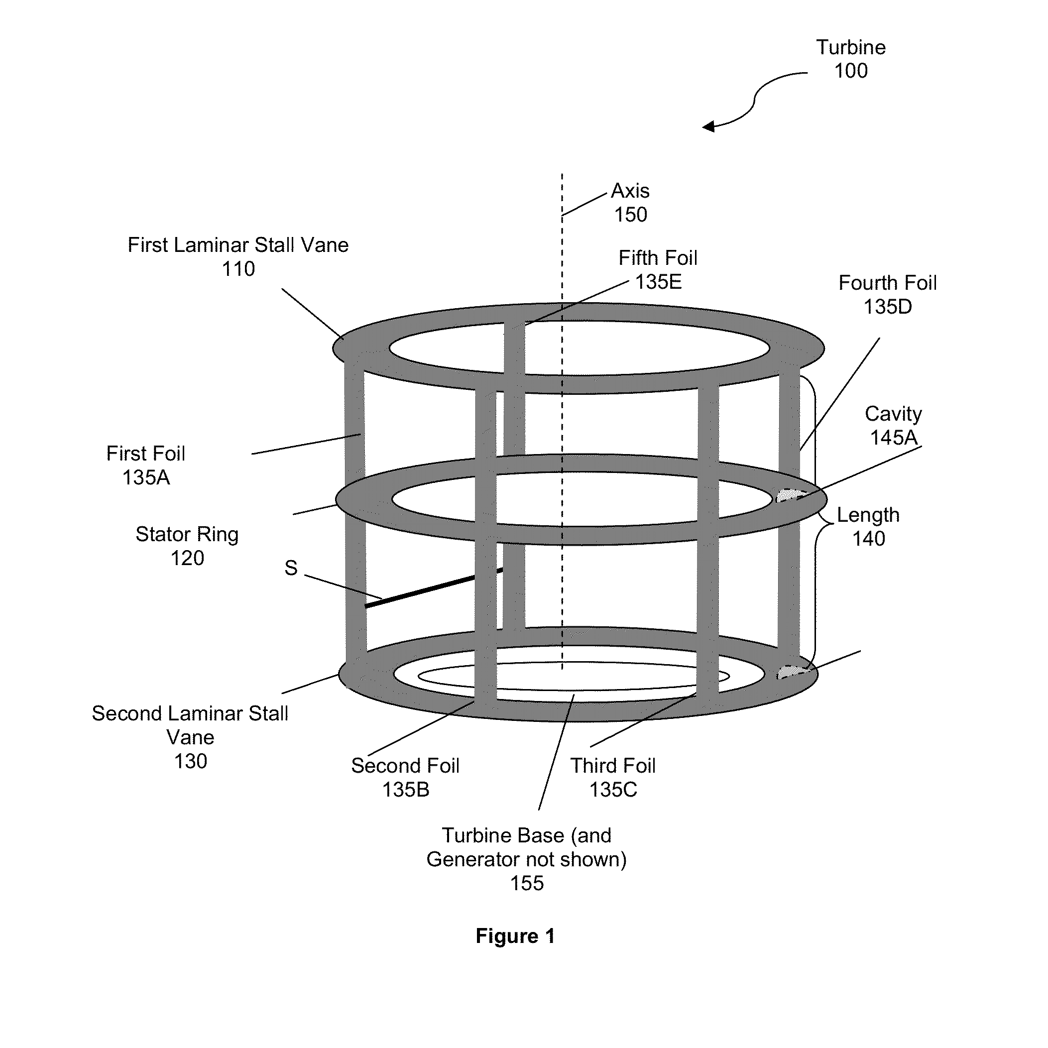
[0022]Applicant has invented lift-based vertical axis wind turbines that have laminar flow foils, and are at least 50%, more preferably at least 70%, or even more preferably at least 80% efficient, or even 110% efficient (where efficiency is determined with respect to the Betz limit—a rule that no turbine can capture more than 59.3% of the kinetic energy in wind). Turbines of the inventive subject matter surpass Betz law / limit because the foils generate power throughout the 360 degree radial (e.g., downwind, crosswind, upwind, etc.) via their unique geometry and spacing. More specifically, Betz law calculations do not apply to turbines of the inventive subject matter where ...


PUM


Abstract

Vertical axis wind turbines are provided having foil design and geometry that facilitates lift, torque and laminar flow along a 360 degree radial. Contemplated foils are non-planar, and have a chord length that is at least three times greater than a distance between a trailing end of a leading foil, and a leading end of a trailing foil. Additionally or alternatively, the foils are located away from a turbine axis at a distance that is about 2.9-3.5 times greater than a chord length of the foils. In some embodiments, the foils are circumferentially distributed via one or more laminar stall vanes.

Description

[0001]This application is a continuation in part of U.S. application Ser. No. 14 / 290,741, filed on May 29, 2014, which claims priority to 61 / 828410, filed May 29, 2013. These and all other extrinsic materials identified herein are incorporated by reference to the same extent as if each individual publication or patent application were specifically and individually indicated to be incorporated by reference. Where a definition or use of a term in an incorporated reference is inconsistent or contrary to the definition of that term provided herein, the definition of that term provided herein applies and the definition of that term in the reference does not apply.FIELD OF THE INVENTION[0002]The field of the invention is wind power technologies.BACKGROUND[0003]The background description includes information that may be useful in understanding the present invention. It is not an admission that any of the information provided herein is prior art or relevant to the presently claimed inventio...

Claims


Application Information

Patent Timeline
Patent Type & Authority Applications(United States)
IPC IPC(8): F03D1/06
CPCF03D1/0633H02K21/24H02K1/32H02K2213/03H02P9/02H01F7/0221H01F7/0273H02P9/00F03D3/061F03D3/062F05B2240/211F05B2240/301Y02E10/74H02K3/28H02K3/47H02K7/1823F03D3/064Y02B10/30Y02E10/72H02K1/2795H02K1/06H02K9/02
Inventor OELOFSE, RUDOLPH
Owner MAGNELAN TECH INC
Why Eureka
Try Eureka