
Aero seat post mounting device

a technology for mounting devices and seat posts, which is applied in the direction of foldable cycles, cycle equipment, cycles, etc., can solve the problems of increased weight, stress concentration, and limited structural strength of carbon fiber compared to aluminum, and achieve the effect of reducing aerodynamic drag and promoting laminar flow over the grommets

Active Publication Date: 2013-09-24
FELT RACING
View PDF17 Cites 5 Cited by
  • Summary
  • Abstract
  • Description
  • Claims
  • Application Information

AI Technical Summary

Benefits of technology

This patent describes a way to attach a seat post made from carbon fiber to a seat tube using bushings and bolts. The seat post has elongated slots along its height, which allows the bushings to be inserted without creating stress concentrations that could lead to failure. The seat post is inserted into the seat tube and its height is adjusted, then bolts are inserted into the seat tube to clamp the seat post and bushings together, reducing stress concentrations. This method allows for a thinner seat post to be used, improving weight and time trials. The seat post also has elongate slots and grommets to promote smooth laminar flow and reduce aerodynamic drag.

Problems solved by technology

Unfortunately, carbon fiber has structural strength limitations compared to aluminum.
Unfortunately, due to the oval cross-section of the seat post, the clamp for mounting the seat post to the seat tube presses on the seat post unevenly thereby causing stress concentrations.
The increased thickness causes increased weight.
Increased weight causes the rider to be slower.
Also, it is more difficult to obtain a tight fit between the seat post and the seat tube with carbon fiber.
The loose fit between the seat post and the seat tube and the non-round configuration of the seat post create an environment where point concentrations are applied to the seat post and promote failure of the seat post.

Method used


Image

  • Aero seat post mounting device
  • Aero seat post mounting device
  • Aero seat post mounting device

Examples


Embodiment Construction

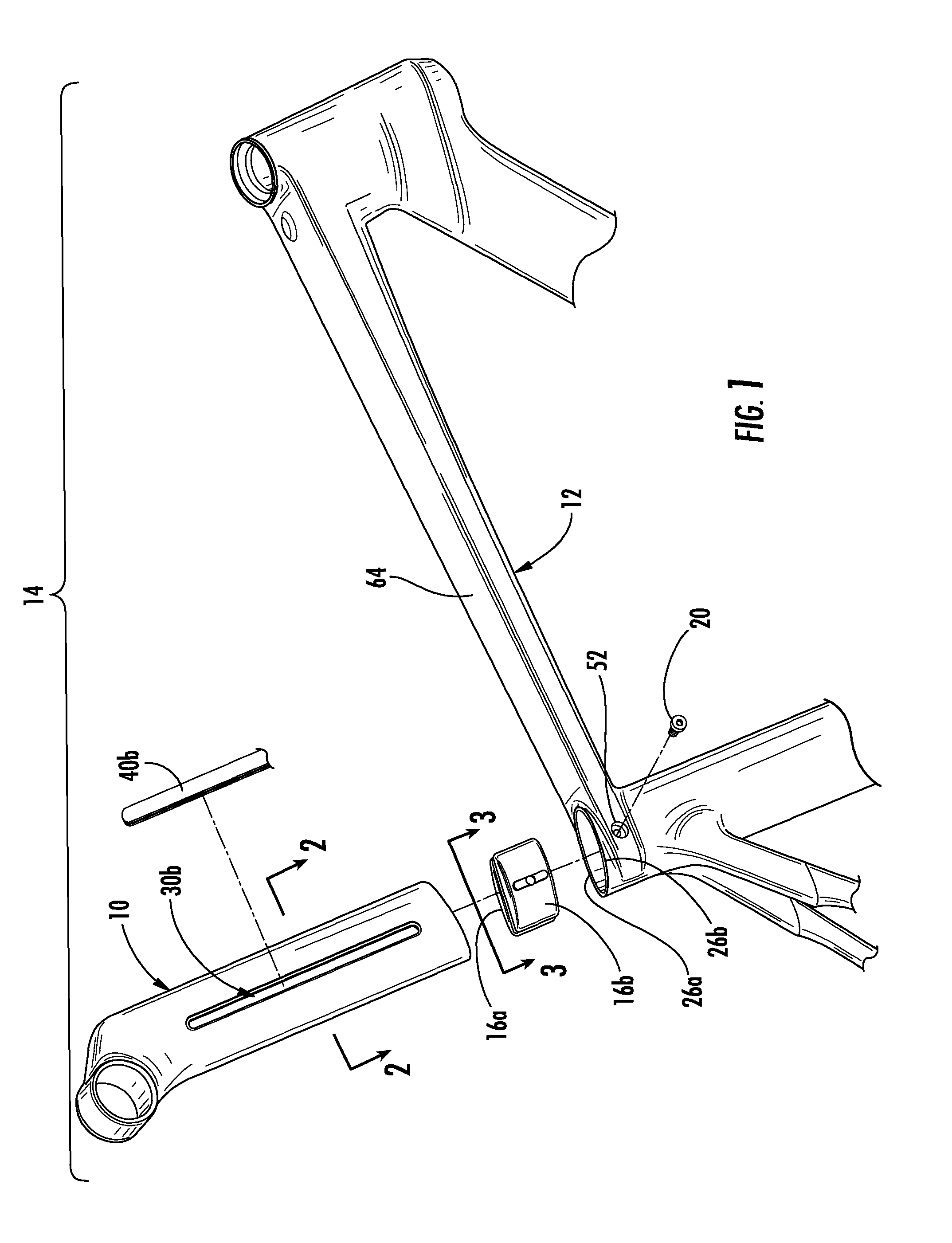
[0031]Referring now to the drawings, a lightweight aerodynamically shaped seat post 10 mounted to a seat tube 12 of a bicycle 14 is shown. The seat post 10 is secured to the seat tube 12 by way of left and right bushings 16a, b. These bushings 16a, b are disposed within a hollow center 18 (see FIG. 2) of the seat post 10 and can slide up and down a height of the seat post 10 during vertical adjustment of the seat post 10. The vertical position of the seat post 10 is adjustable based on the rider's physical geometry. Left and right bolts 20 may pass through each side of the seat tube 12 / top tube 64 and be threaded into a threaded hole 22 (see FIG. 5) of the bushings 16a, b. As shown in FIG. 6, the bolts 20 may be tightened to clamp the left sidewall 24a of the seat post 10 to the left sidewall 26a of the bicycle frame (i.e., junction of the top tube 64 and seat tube 12) and clamp the right sidewall 24b of the seat post 10 to the right sidewall 26b of the bicycle frame. In this manner...


PUM


Abstract

An aerodynamically shaped seat post fabricated from carbon fiber is mountable to a seat tube by placing left and right bushings within the hollow center of the seat post. These bushings are accessible and engageable to left and right bolts when the desired height of the seat post is reached. In particular, the left and right bolts are fed through left and right holes formed in the seat tube. The seat post has left and right elongate slots which provide access to the bushings, and more particularly, to the threaded holes of the bushings so that the left and right bolts may engage those threaded holes and clamp the left and right sidewalls of the seat post and the left and right sidewalls of the seat tube together, respectively. This seat post mount eliminates stress concentrations to the seat post. Moreover, the seat post is not clamped down with opposed forces placed on the left and right sidewalls of the seat post.

Description

CROSS-REFERENCE TO RELATED APPLICATIONS[0001]Not ApplicableSTATEMENT RE: FEDERALLY SPONSORED RESEARCH / DEVELOPMENT[0002]Not ApplicableBACKGROUND[0003]The various embodiments disclosed herein are directed to a mounting device and method for securing an aerodynamically shaped seat post to a seat tube of a bicycle.[0004]Traditional bicycles are typically fabricated from a metallic material such as aluminum for the purposes of balancing strength and weight. Current methods of manufacturing high-end bicycles involve the use of fabricating the various components of the bicycle including but not limited to the frame and seat post with carbon fiber material. The benefit of utilizing carbon fiber is that it is significantly lighter than aluminum. Unfortunately, carbon fiber has structural strength limitations compared to aluminum. By way of example and not limitation, carbon fiber material is more susceptible to breakage when exposed to a point concentration or a stress concentration.[0005]In...

Claims


Application Information

Patent Timeline
Patent Type & Authority Patents(United States)
IPC IPC(8): B62K19/00
CPCB62K19/02B62J1/08B62K19/36
Inventor SOUCEK, JEFF
Owner FELT RACING
Learn More