Dispensing dish brush

Active Publication Date: 2008-12-09
BRADSHAW INT
View PDF7 Cites 26 Cited by
  • Summary
  • Abstract
  • Description
  • Claims
  • Application Information

AI Technical Summary

Benefits of technology

[0006]A dispensing dish brush is described that comprises a cleaning head, a handle and a neck. The cleaning head has a face that includes a plurality of bristles and one or more apertures. The cleaning head has a wall that defines a first portion of a reservoir. The handle has a flexible wall that defines a second portion of the reservoir. A diaphragm is connected to the inner side of the wall of the handle. The neck connects the handle and the cleaning head. The neck has a wall that defines a third portion of the reservoir. The first portion of the reservoir, the second portion the reservoir, the third portion of the reservoir and the apertures are in fluid communication.
[0007]A first position of the dispensing dish brush wherein the handle defines a first distance between the diaphragm and an opposing wall of the handle and a second position of the dispensing dish brush wherein the handle i

Problems solved by technology

This process can be frustrating when the cleaning liquid runs or drips off an inclined area that needs to be cleaned.
In this all too common situation, the cleaning liquid does not get adequately absorbed into the area and excessive force needs to be applied by the dispensing dish brush to clean the area.

Method used


Image

  • Dispensing dish brush
  • Dispensing dish brush
  • Dispensing dish brush

Examples


Embodiment Construction

[0019]Although specific terms are used in the following description for sake of clarity, these terms are intended to refer only to particular structures of the invention selected for illustration in the drawings, and are not intended to define or limit the scope of the invention.

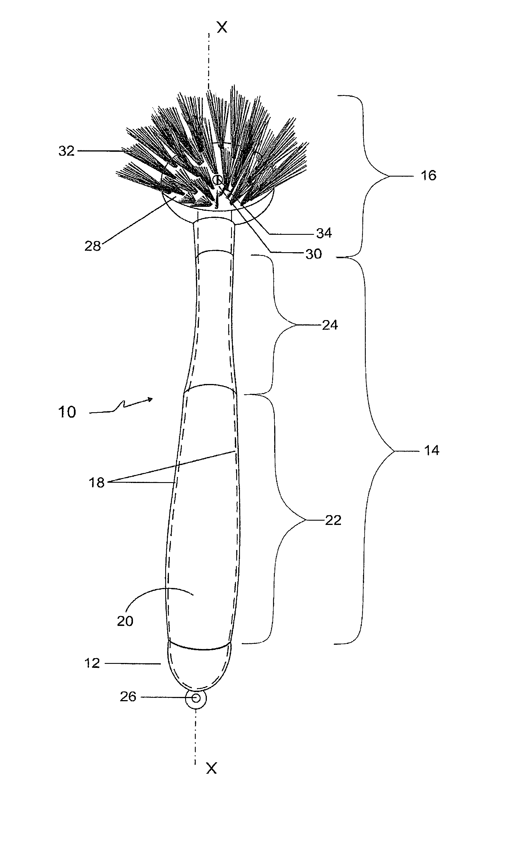
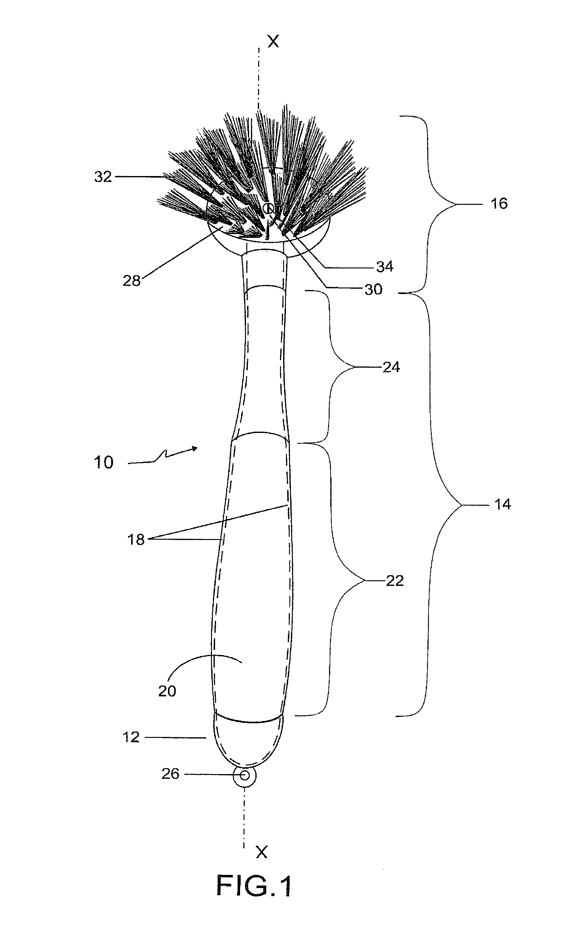
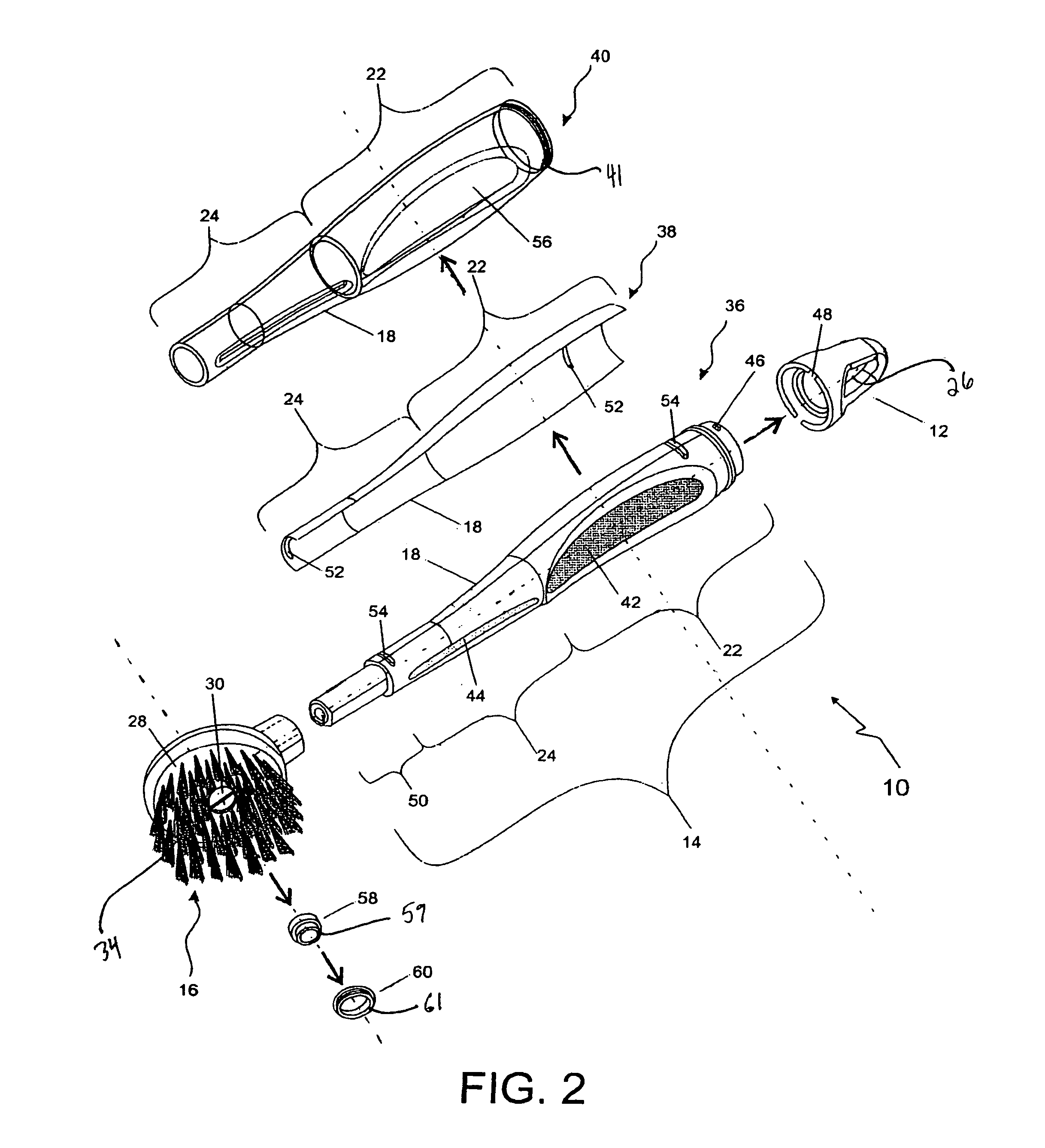
[0020]Referring now to FIG. 1, a dispensing dish brush 10 includes a cap 12, a handle portion 14 and a cleaning head 16. Brush 10 has a proximal end portion and a distal end portion that define a central longitudinal axis-X. The proximal end portion of brush 10 includes cap 12 and the distal end portion of brush 10 includes cleaning head 16. Cap 12 and handle portion 14 have walls 18 that define a reservoir 20 for the storage and dispensing of a cleaning liquid.

[0021]Handle portion 14 includes a gripping portion 22 and a neck portion 24. Gripping portion 22 and neck portion 24 are approximately cylindrical tubes. Gripping portion 22 and neck portion 24 taper the interior dimensions of reservoir 20 in the dis...


PUM


Abstract

A dispensing dish brush includes a cap, a handle portion and a cleaning head. The cap and the handle portion define a common wall that defines a reservoir. The reservoir stores and dispenses a cleaning liquid. The handle portion includes a gripping portion and a neck portion. The gripping portion includes a core section, a middle section and an upper section that define a diaphragm. The neck portion has an extension portion that connects to the cleaning head. The cleaning head includes a plurality of bristles and an aperture with a wall. The aperture is placed with a removable valve and valve lock to restrict the flow of the cleaning liquid. The diaphragm is squeezable and flexes to dispense the cleaning liquid. The diaphragm accelerates the flow of the cleaning liquid in the reservoir. The cap provides access to the reservoir.

Description

BACKGROUND[0001]1. Field of the Invention[0002]The present invention relates to hand held cleaning implements and more particularly to a hand held dispensing dish brush that dispenses a liquid.[0003]2. Description of the Related Art[0004]Hand held dispensing dish brushes are commonly used with a separate bottle of cleaning liquid. The cleaning liquid is applied to an area and then the hand held cleaning implement or brush is used to scrub that area. This process can be frustrating when the cleaning liquid runs or drips off an inclined area that needs to be cleaned. In this all too common situation, the cleaning liquid does not get adequately absorbed into the area and excessive force needs to be applied by the dispensing dish brush to clean the area.[0005]A hand held cleaning implement is needed that has an integral ability to dispense a cleaning liquid to an area and simultaneously scrub that same area. A cleaning implement is further needed that has an enhanced ability to dispense...

Claims


Application Information

Patent Timeline
IPC IPC(8): A46B11/04B43M11/06
CPCA46B5/002A46B5/02A46B11/0041A46B2200/3033
Inventor SAMPAIO, ANDRE
Owner BRADSHAW INT
Why Eureka
Try Eureka