
Abnormality analysis system for vehicle and abnormality analysis method for vehicle

a technology of abnormality analysis and abnormality analysis, which is applied in vehicle maintenance, instruments, nuclear elements, etc., can solve the problems of high processing load placed on the failure analysis unit during the failure analysis, and achieve the effect of reducing processing load and improving the accuracy of determination of abnormality causes

Inactive Publication Date: 2010-03-04
TOYOTA JIDOSHA KK
View PDF3 Cites 25 Cited by
  • Summary
  • Abstract
  • Description
  • Claims
  • Application Information

AI Technical Summary

Benefits of technology

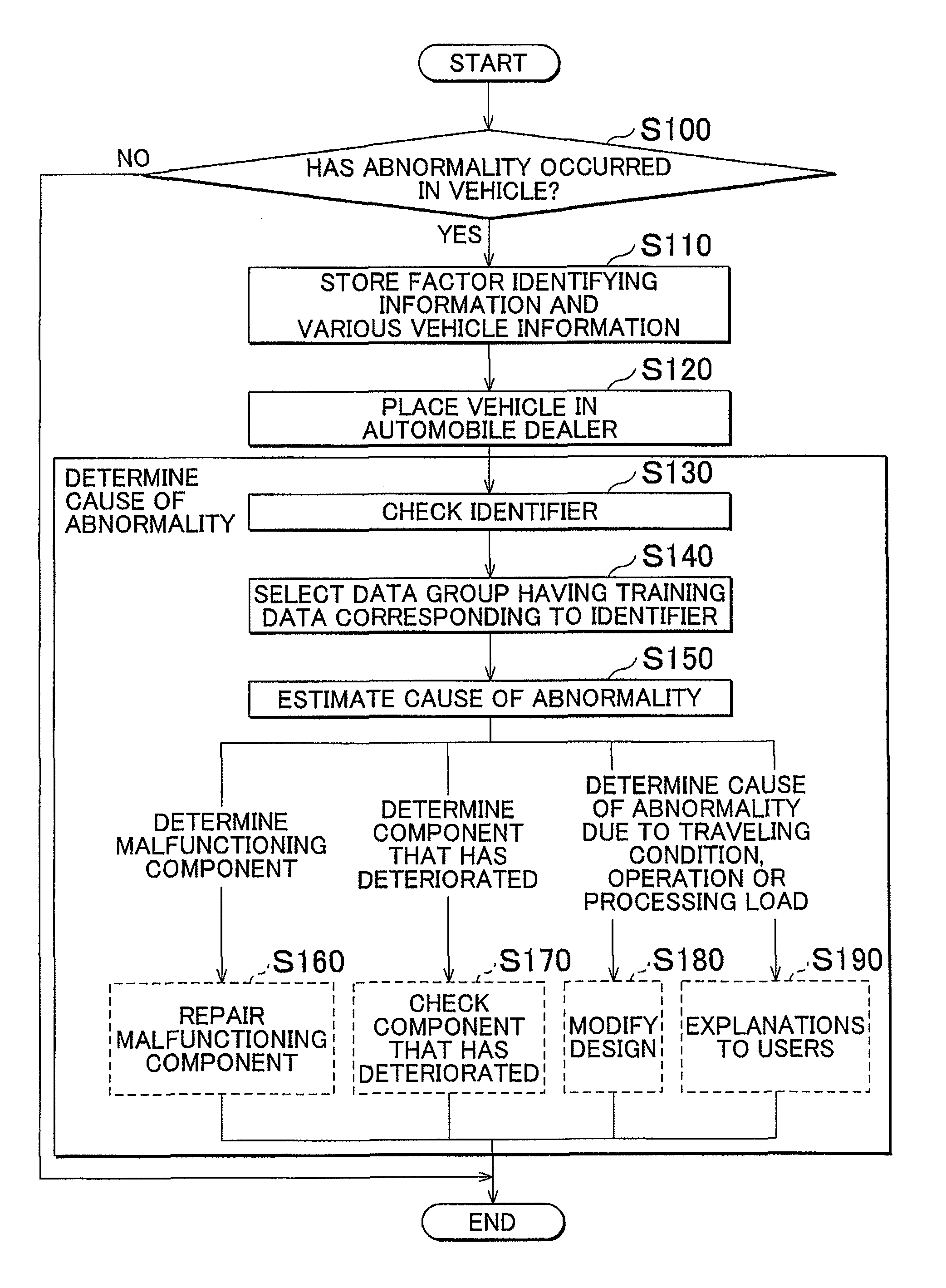
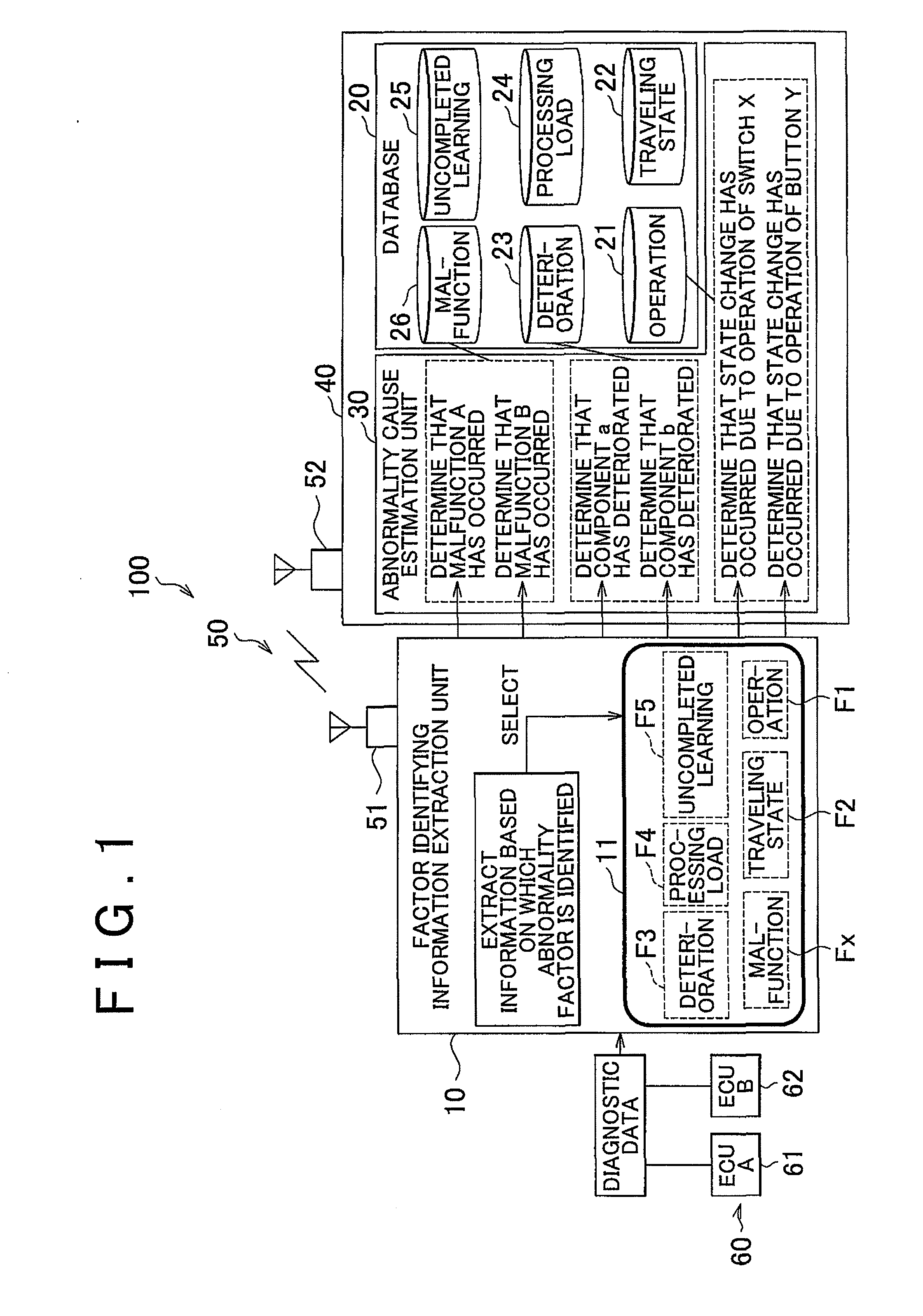
The invention provides an abnormality analysis system and method for a vehicle that can detect and identify abnormalities with a reduced processing load. The system includes a factor identifying information extraction unit that extracts information that identifies the cause of the abnormality, a database that contains data groups that correspond to categories of abnormalities and their corresponding causes, and an abnormality cause estimation unit that selects the data group that corresponds to the extracted factor identifying information and estimates the cause of the abnormality. The system can also include a communication unit that transmits the factor identifying information in real-time to an external diagnostic unit. The method includes extracting factor identifying information, selecting a data group, and estimating the cause of the abnormality. Overall, the system and method improve the accuracy and efficiency of analyzing abnormalities in vehicles.

Problems solved by technology

However, because the failure analysis unit described in JP-A-2006-251918 analyzes the failure with the use of the entire failure information stored in the shared information database, a high processing load is placed on the failure analysis unit during the failure analysis.

Method used


Image

  • Abnormality analysis system for vehicle and abnormality analysis method for vehicle
  • Abnormality analysis system for vehicle and abnormality analysis method for vehicle
  • Abnormality analysis system for vehicle and abnormality analysis method for vehicle

Examples


Embodiment Construction

[0029]Hereafter, an embodiment of the invention will be described with reference to the accompanying drawings.

[0030]FIG. 1 is a view showing an example of the overall structure of an abnormality analysis system 100 according to an embodiment of the invention. As shown in FIG. 1, the abnormality analysis system 100 according to the embodiment of the invention includes a factor identifying information extraction unit 10, a database 20, and an abnormality cause estimation unit 30. The database 20 and the abnormality cause estimation unit 30 may be formed integrally with each other as a vehicle exterior diagnostic unit 40, and provided outside a vehicle. When the database 20 and the abnormality cause estimation unit 30 are formed integrally with each other as the vehicle exterior diagnostic unit 40, the abnormality analysis system 100 according to the embodiment of the invention may further include a communication unit 50.

[0031]When an abnormality of the vehicle is detected, the factor ...


PUM


Abstract

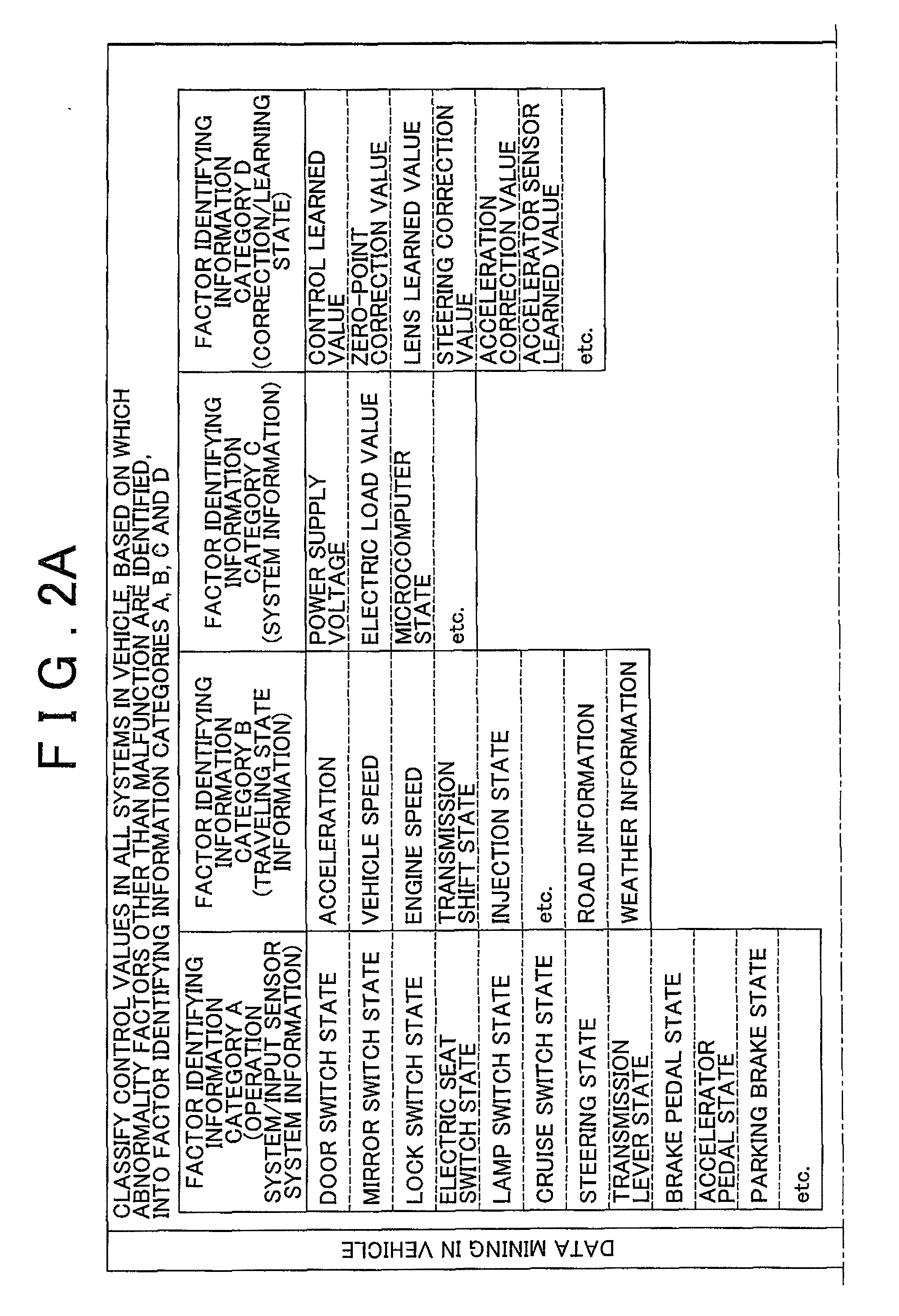
When an abnormality of a vehicle is detected based on a vehicle state value that indicates the vehicle state, an abnormality analysis system for the vehicle estimates a cause of the abnormality. The abnormality analysis system includes: a factor identifying information extraction unit that extracts factor identifying information which is used to identify a factor of the abnormality based on the vehicle state value; a database that contains data groups which correspond to respective categories of the factor identifying information and which store causes of abnormalities and vehicle state values at the time of occurrence of the abnormalities; and an abnormality cause estimation unit that executes a process for estimating the cause of the abnormality of the vehicle with the use of the data group that corresponds to the category of the factor identifying information extracted by the factor identifying information extraction unit.

Description

INCORPORATION BY REFERENCE[0001]The disclosure of Japanese Patent Application No. 2008-222459 filed on Aug. 29, 2008 including the specification, drawings and abstract is incorporated herein by reference in its entirety.BACKGROUND OF THE INVENTION[0002]1. Field of the Invention[0003]The invention relates generally to an abnormality analysis system for a vehicle and an abnormality analysis method for a vehicle. More specifically, the invention relates to an abnormality analysis system for a vehicle and an abnormality analysis method for a vehicle, which are used to estimate the cause of an abnormality if it is determined that an abnormality has occurred in a vehicle based on a vehicle state value which indicates the vehicle state.[0004]2. Description of the Related Art[0005]For example, Japanese Patent Application Publication No. JP-A-2006-251918 (JP-A-2006-251918) describes a failure analysis system that includes multiple in-vehicle sensors which constantly obtain the state informat...

Claims


Application Information

Patent Timeline
Patent Type & Authority Applications(United States)
IPC IPC(8): G06F7/00B60S5/00G05B23/02G06F17/30G06Q50/00G06Q50/10G06Q50/30
CPCG07C5/085G07C5/008
Inventor ISHIKAWA, TOMOYASUABE, TOSHIYUKI
Owner TOYOTA JIDOSHA KK
Learn More