
Actuating Device for a Motorized Wheeled Vehicle with an Electric Generating Function

a technology of motorized wheels and actuators, which is applied in the direction of magnetic circuit rotating parts, magnetic circuit shape/form/construction, transportation and packaging, etc., can solve the problems of limiting the movement of bicycles, and achieve the effects of promoting magnetic interaction, accelerating rotation speed, and replenishing electric power of bicycles

Inactive Publication Date: 2010-03-04
LIN WEI TING
View PDF7 Cites 16 Cited by
  • Summary
  • Abstract
  • Description
  • Claims
  • Application Information

AI Technical Summary

Benefits of technology

[0008]A further objective of the present invention is to provide an actuating device, wherein when the bicycle is padelled by a rider or traveled on a downward slope, the actuating device has a generating function to produce an electric current which is delivered to the battery of the bicycle so as to replenish the electric power of the bicycle.
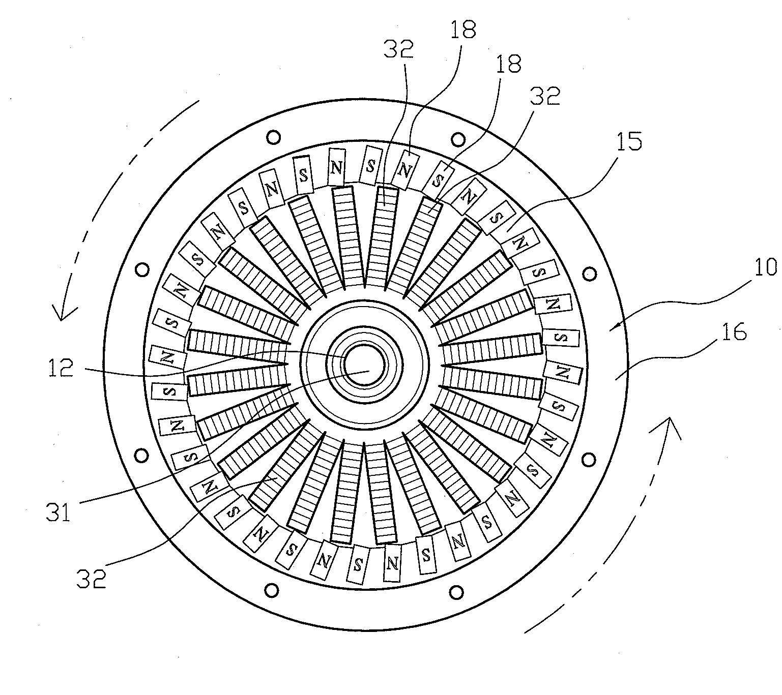
[0009]A further objective of the present invention is to provide an actuating device, wherein each of the magnets of the rotation unit is inclined relative to a respective one of the coils of the fixed unit, so that each of the magnets is closer to any two adjacent coils to promote the magnetic interaction between each of the magnets and any two adjacent coils so as to accelerate the rotation speed and to enhance the rotation efficiency of the rotation unit.
[0011]A further objective of the present invention is to provide an actuating device, wherein each of the magnetically conductive plates has a high magnetic conductivity and a high heat radiating efficiency.

Problems solved by technology

However, the electric power supplied by the storage battery is limited so that the storage battery cannot be used to satisfy the larger power requirement of the bicycle during a long period of time, thereby limiting movement of the bicycle.

Method used


Image

  • Actuating Device for a Motorized Wheeled Vehicle with an Electric Generating Function
  • Actuating Device for a Motorized Wheeled Vehicle with an Electric Generating Function
  • Actuating Device for a Motorized Wheeled Vehicle with an Electric Generating Function

Examples


Embodiment Construction

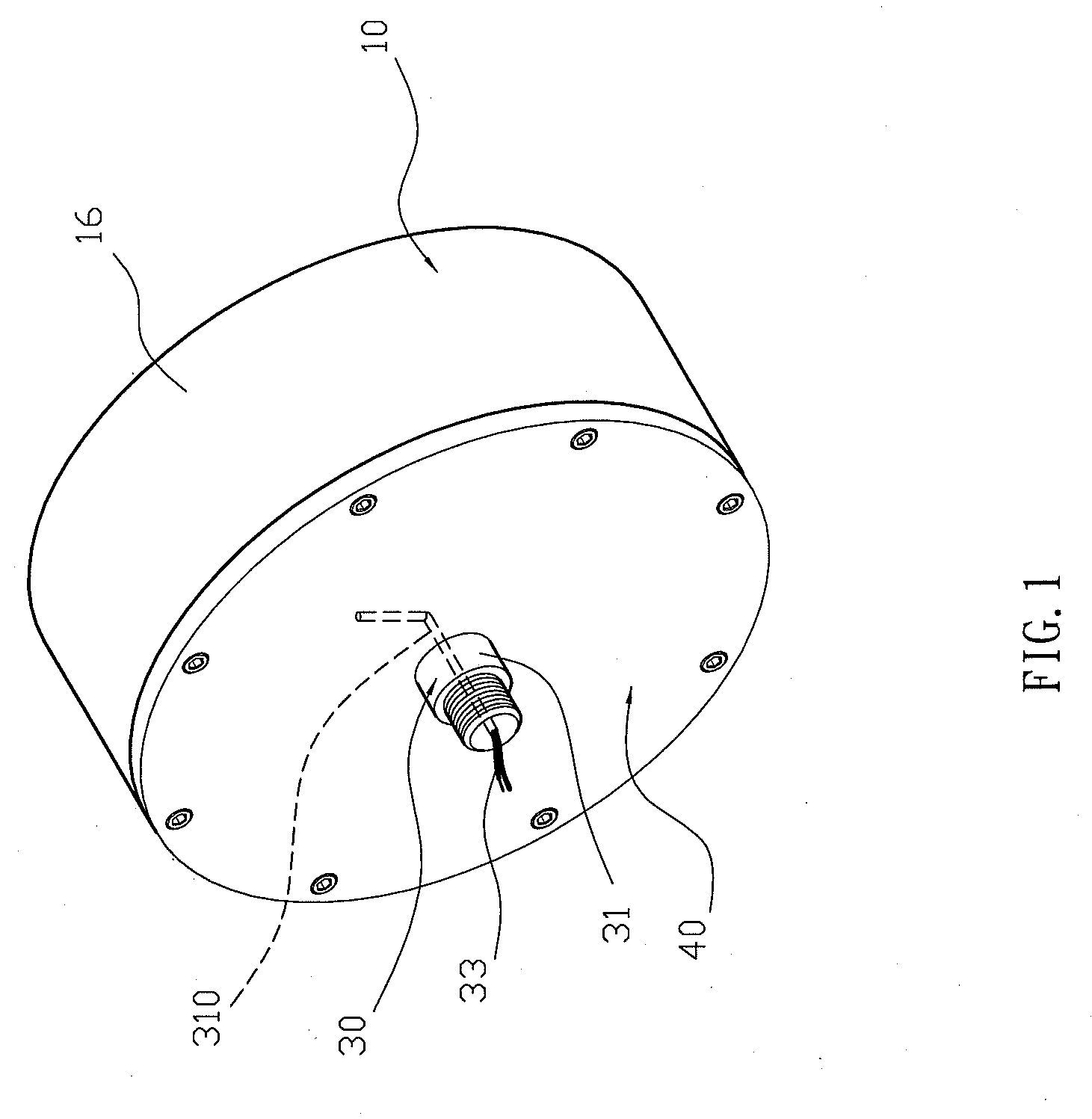
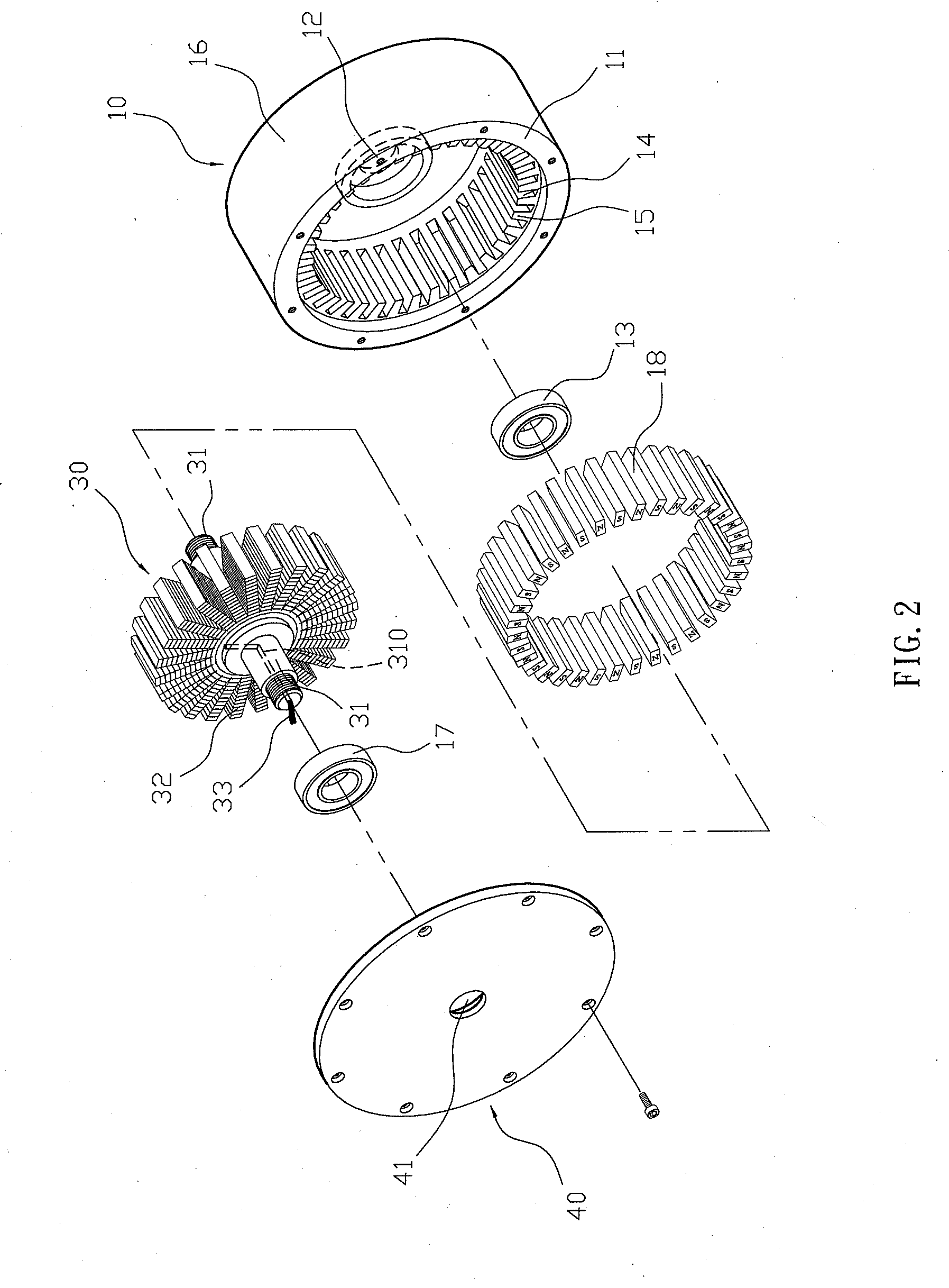
[0018]Referring to the drawings and initially to FIGS. 1-4, an actuating device for a motorized bicycle in accordance with the preferred embodiment of the present invention comprises a fixed unit 30, a rotation unit 10 rotatably mounted on the fixed unit 30, and an outer cover 40 mounted on the rotation unit 10 to cover the fixed unit 30.

[0019]The fixed unit 30 includes a mandrel 31, a plurality of coils 32 mounted on the mandrel 31 and arranged in a radiating manner, and an electric wire 33 electrically connected to each of the coils 32 to supply an electric power to each of the coils 32. The mandrel 31 of the fixed unit 30 has an inner portion provided with a channel 310 to allow passage of the electric wire 33. Each of the coils 32 of the fixed unit 30 is directed in a radial direction that extends radially and outwardly from the mandrel 31. In the preferred embodiment of the present invention, the fixed unit 30 includes twenty-four coils 32.

[0020]The rotation unit 10 includes an...


PUM


Abstract

An actuating device for a motorized bicycle includes a fixed unit and a rotation unit. The fixed unit includes a mandrel and a plurality of coils. The rotation unit includes a rotation member and a plurality of magnets. Each of the magnets is inclined relative to a respective one of the coils so that each of the magnets is closer to any two adjacent coils to promote the magnetic interaction between each of the magnets and any two adjacent coils so as to enhance the rotation efficiency of the rotation unit. When the bicycle is padelled by a rider or traveled on a downward slope, the actuating device has a generating function to produce an electric current so as to replenish the electric power of the bicycle.

Description

BACKGROUND OF THE INVENTION[0001]1. Field of the Invention[0002]The present invention relates to an actuating device and, more particularly, to an actuating device for a motorized wheeled vehicle, such as a motorized bicycle and the like.[0003]2. Description of the Related Art[0004]A conventional motorized bicycle comprises a storage battery which supplies an electric power to rotate a front wheel or rear wheel so as to move the bicycle forward automatically without needing padelling of a rider so as to save the rider's energy. However, the electric power supplied by the storage battery is limited so that the storage battery cannot be used to satisfy the larger power requirement of the bicycle during a long period of time, thereby limiting movement of the bicycle.BRIEF SUMMARY OF THE INVENTION[0005]In accordance with the present invention, there is provided an actuating device, comprising a fixed unit and a rotation unit rotatably mounted on the fixed unit. The fixed unit includes a...

Claims


Application Information

Patent Timeline
Patent Type & Authority Applications(United States)
IPC IPC(8): H02K1/27
CPCH02K1/2786Y02T10/641H02K21/22Y02T10/64H02K1/2791
Inventor LIN, WEI-TING
Owner LIN WEI TING
Learn More