
Car flashlight structure

Inactive Publication Date: 2006-12-07
SHEEN TIENG TENG
View PDF4 Cites 19 Cited by
  • Summary
  • Abstract
  • Description
  • Claims
  • Application Information

AI Technical Summary

Benefits of technology

[0008] Hence, a primary objective of the present invention is to provide a car flashlight structure, wherein a unique assembly of the flashlight effectively minimizes the physical size of the flashlight, thereby reducing the space occupied by the flashlight when not in use. Moreover, the present invention is able to conveniently use a car charger to replenish electric power in the flashlight, thereby achieving the need for convenience of use and safety when driving.
[0010] According to the aforementioned structure, the car flashlight of the present invention can be plugged into the charger in a car to replenish electric power. When wanting to use the flashlight, the user takes out the flashlight from the charger and directly pushes the cap forward to actuate the acting face, which causes the contact switch to make an electrical connection that provides an electric current to the LED light of the illumination assembly, thereby enabling the LED light to emit light that provides the user with auxiliary illumination.

Problems solved by technology

However, the overhead night light is of a fixed type that only projects light downwards, thereby leaving many dead angles where the light does not illuminate.
Moreover, if the user wants to conduct tasks outside the car where there is no lighting, the user is unable to use the overhead night light in the car interior for auxiliary illumination.
If battery power is exhausted when using the flashlight, then electric power required by the flashlight cannot be replenished.
However, the conventional car flashlight is oversized, and the majority of conventional car cigarette lighter connectors are fitted at a side of the gear lever, which takes up space when charging the flashlight, and hinders driving the car, thus increasing the risk of a car accident.

Method used


Image

  • Car flashlight structure
  • Car flashlight structure
  • Car flashlight structure

Examples


Embodiment Construction

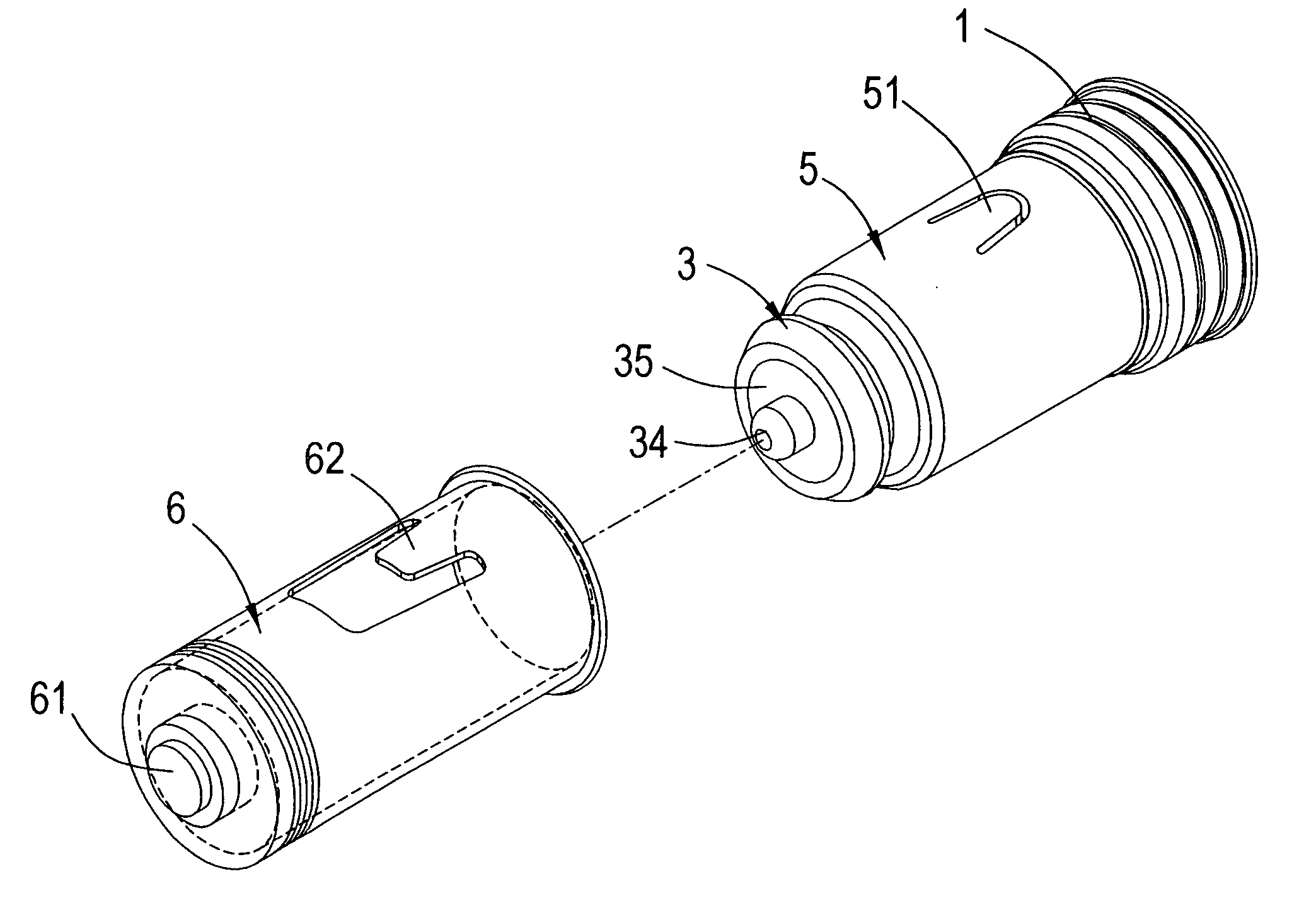
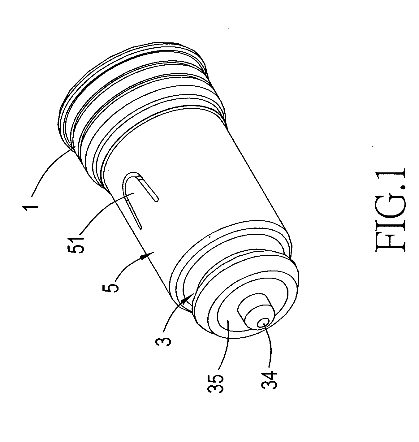
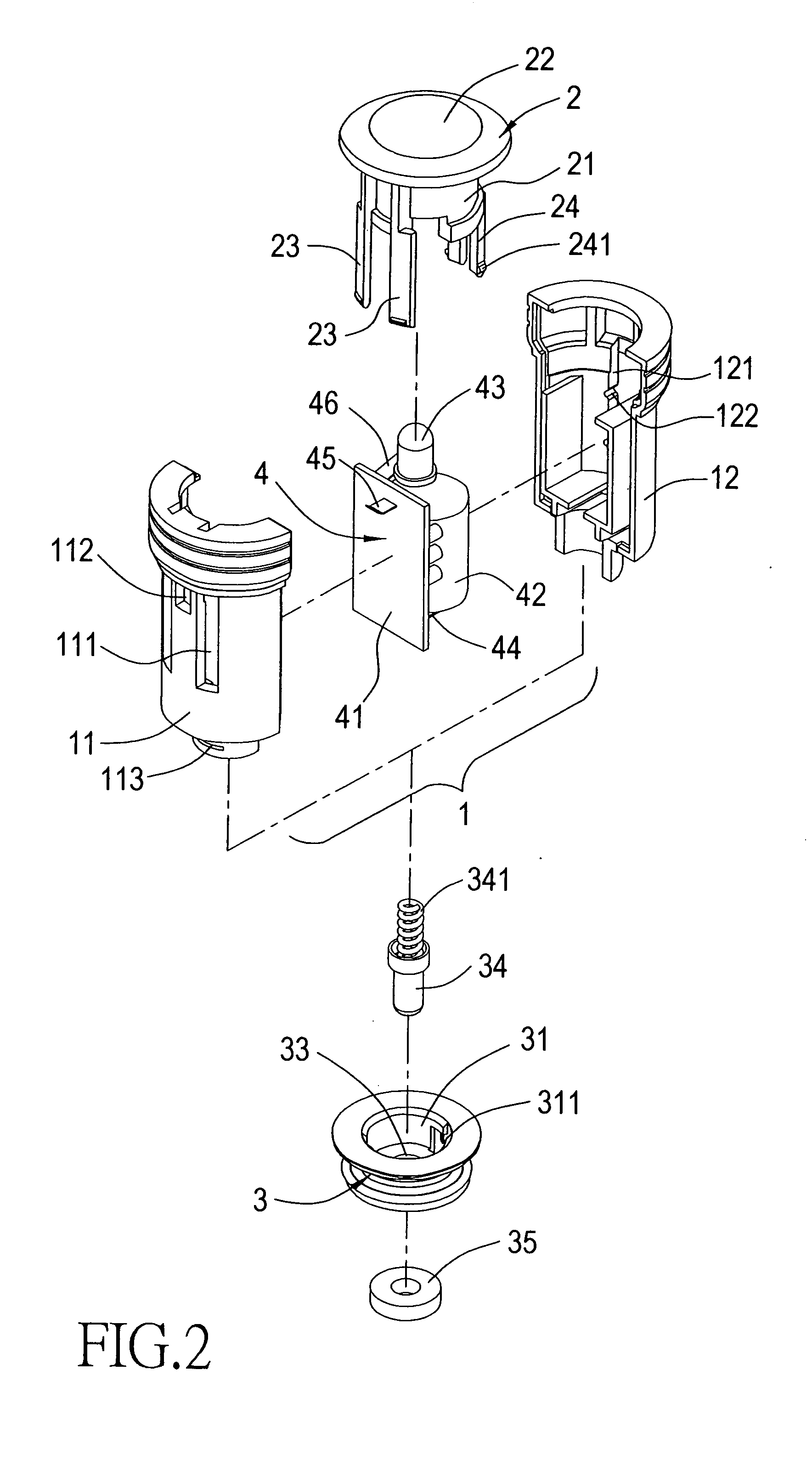
[0030] Referring to FIGS. 1, 2 and 3, which show the present invention structured to comprise a cylindrical body 1, a cap 2, a casing cover 3, an illumination assembly 4 and an outer cylinder 5.

[0031] Referring to FIGS. 2, 3 and 4, the cylindrical body 1 comprises a first casing 11 reciprocally combined with a corresponding second casing 12. At least one first slide track 111 is defined on a surface of the first casing 11, and at least one second slide track 121 is defined on a surface of the second casing 121. Moreover, a set of positioning grooves 122 are respectively defined on two ends within the second slide track 121, and a through hole 112 is defined at an appropriate position in the first casing 11. Furthermore, a protruding catch 113 is configured on a surface of a rear end of the first casing 11 of the cylindrical body 1.

[0032] Referring to FIGS. 2, 3, 7, 8, 9, 10, 14 and 15, the cap 2 is disposed on a front end of the aforementioned cylindrical body 1. The cap is provid...


PUM


Abstract

A car flashlight structure, which can be plugged into a car charger, consisting of a cylindrical body, a cap disposed on a front end of the cylindrical body, a casing cover socket joined to the cap and an illumination assembly disposed within the cylindrical body. The illumination assembly is provided with at least one accumulator unit, at least one LED light, and configured with a contact switch. According to the aforementioned structure, the car flashlight can be plugged into a conventional car charger to replenish electric power, and is taken out directly from the charger to use, whereupon the cap is pushed forward to actuate the contact switch and provide an electric current to the LED light of the illumination assembly, thereby furnishing the user with auxiliary illumination.

Description

BACKGROUND OF THE INVENTION [0001] (a) Field of the Invention [0002] The present invention relates to a car flashlight structure, and more particularly to a flashlight that is able to provide car interior illumination, and that facilitates using a car charger to replenish electric power. Moreover, a unique assembly of the flashlight effectively minimizes the physical size, thereby reducing the space occupied by the flashlight and facilitating storing away when not in use. [0003] (b) Description of the Prior Art [0004] Modern people attach great importance to the quality of life, thus, when choosing a car, buying a car or purchasing car accessories, apart from the requirements for operability and comfort, importance has also began to be attached to car interior accessories that function together. However, when driving or riding in a car at night, because of the surrounding darkness, if the driver or passenger needs to carry out some task in the car, for instance, look for an article,...

Claims


Application Information

Patent Timeline
IPC IPC(8): B60Q1/26
CPCB60Q3/001B60Q3/007B60Q3/0269F21Y2101/02F21L4/027F21V14/065F21V23/0414B60Q3/0296F21Y2115/10B60Q3/82B60Q3/85B60Q3/88B60Q3/59
Inventor SHEEN, TIENG-TENG
Owner SHEEN TIENG TENG
Learn More