
Substrate processing apparatus and method for transferring substrate for the apparatus

a substrate processing and substrate technology, applied in the direction of electrical apparatus, thin material processing, article separation, etc., can solve the problems of shortened time necessary for cleaning substrates, increased size and chemical consumption of batch processors, and increased time required for substrate transferring and other problems, to achieve the effect of improving the efficiency of substrate transferring

Active Publication Date: 2010-02-25
SEMES CO LTD
View PDF3 Cites 14 Cited by
  • Summary
  • Abstract
  • Description
  • Claims
  • Application Information

AI Technical Summary

Benefits of technology

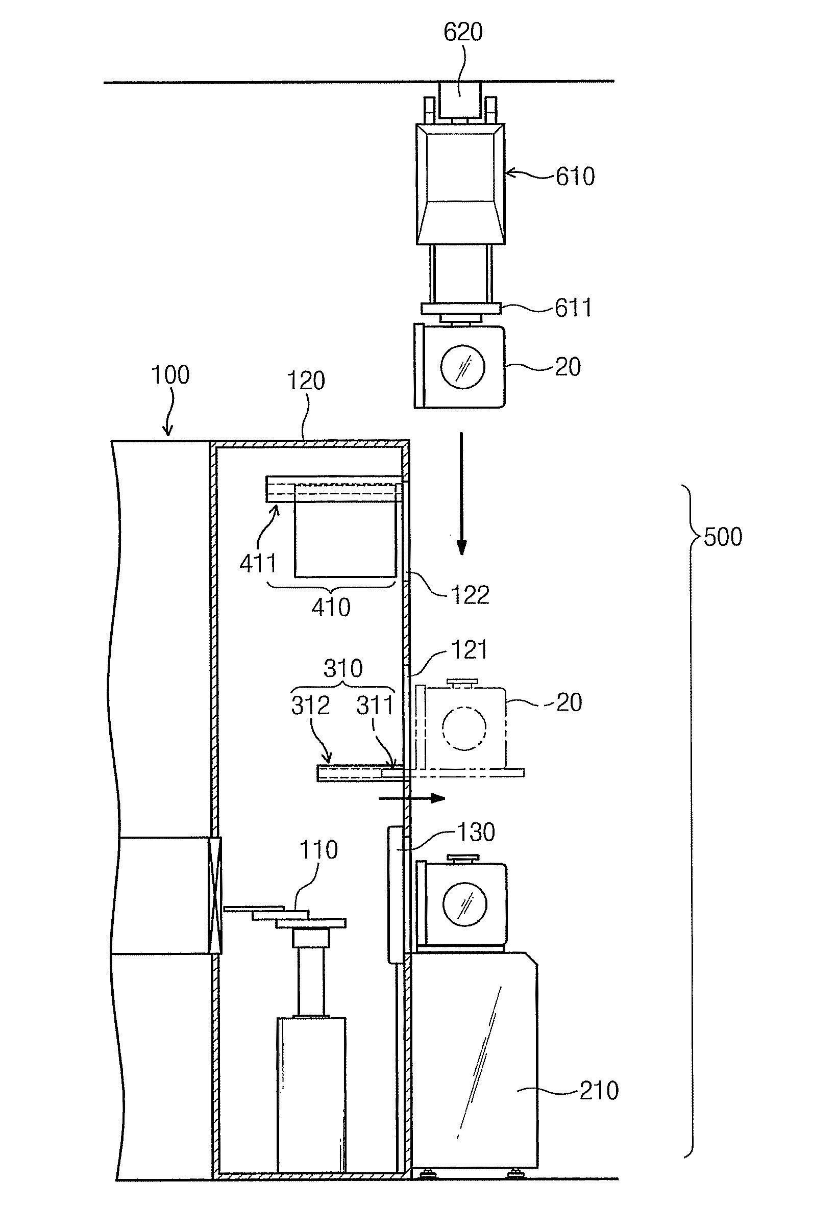
The present invention provides a substrate processing apparatus with improved substrate transferring efficiency. The apparatus includes a process module, a main load unit, a buffer load unit, and at least one transfer unit. The buffer load unit is movable into and outward from the process module and can receive containers accommodating substrates. The transfer unit is movable into and outward from the process module and can transfer containers between the main load unit and the buffer load unit. The methods for transferring substrates involve placing a standby container on the buffer load unit, transferring the container to the process module for processing, and then transferring the processed substrates container to an outside area. The buffer load unit can be moved into the process module when a standby container is transferred or when a container accommodating processed substrates is transferred. The technical effects of the invention include improved substrate transferring efficiency and flexibility in substrate processing.

Problems solved by technology

However, since the sizes of baths of a batch process are proportional to the size of substrates, the size and chemical consumption of the batch processor increase as the size of substrates increases.
Since such an OHT is operated with a low speed, it takes more time to transfer a FOUP using the OHT than to draw uncleaned substrates from the FOUP and put cleaned substrates into the FOUP.
Moreover, the time necessary for cleaning substrates is shortened because the efficiency of a cleaning apparatus is improved owing to the development of related technology; however, the speed of OHTs is still low.
Therefore, FOUPs cannot be efficiently transferred by using an OHT, thereby increasing the idle time of a cleaning apparatus and decreasing the productivity of a manufacturing process.

Method used


Image

  • Substrate processing apparatus and method for transferring substrate for the apparatus
  • Substrate processing apparatus and method for transferring substrate for the apparatus
  • Substrate processing apparatus and method for transferring substrate for the apparatus

Examples


Embodiment Construction

[0027]Preferred embodiments of the present invention will be described below in more detail with reference to the accompanying drawings. In the following description, wafers are described as examples of substrates. However, the scope and spirit of the present invention are not limited thereto.

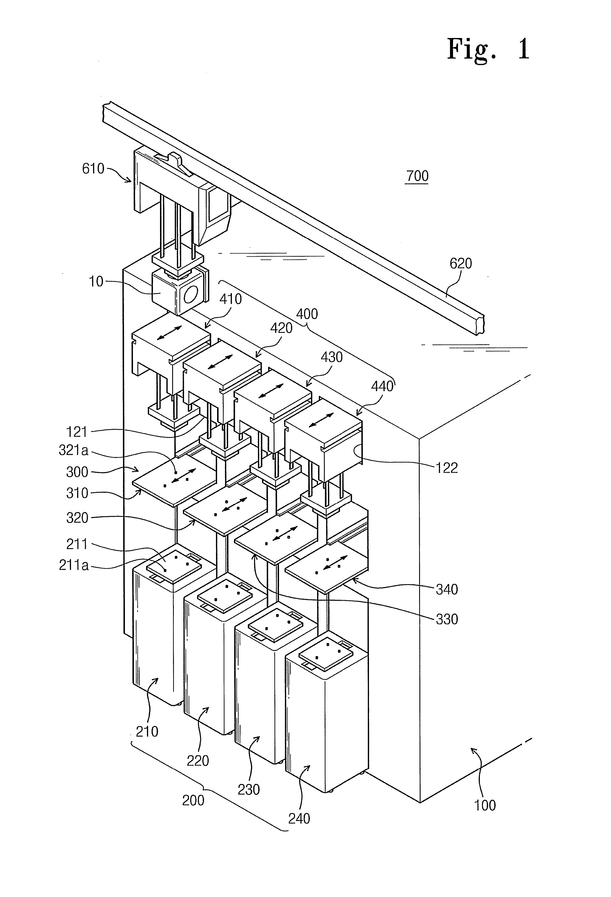
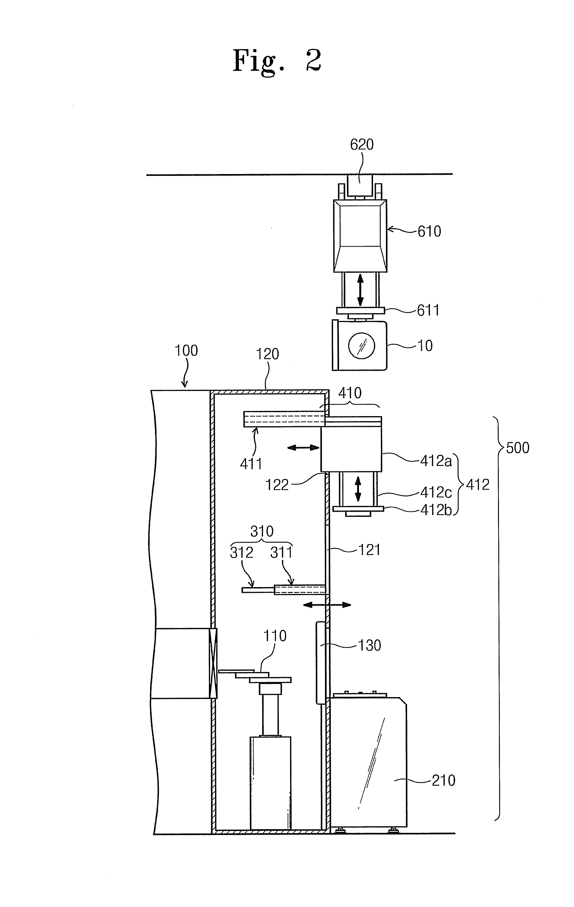
[0028]FIG. 1 is a partial perspective view illustrating an exemplary embodiment of a substrate processing apparatus 700 according to the present invention, and FIG. 2 is a sectional view illustrating the substrate processing apparatus 700 of FIG. 1.

[0029]Referring to FIGS. 1 and 2, the substrate processing apparatus 700 includes a process module 100 and a substrate supply module 500. The process module 100 is configured to process wafers. The substrate supply module 500 is configured to supply wafers (unprocessed wafers) to the process module 100 for processing the wafers and carries the wafers processed in the process module 100 to the outside.

[0030]In detail, unprocessed wafers are supplied t...


PUM


Abstract

A substrate processing apparatus includes a main load unit, a buffer load unit, and a transfer unit. Containers each accommodating substrates are placed on the main load unit and the buffer load unit. The buffer load unit is disposed above the main load unit and movable into and outward from a process module. Therefore, more containers can be placed in the substrate processing apparatus without increasing the footprint of the substrate processing apparatus, and thus it is possible to reduce equipment idle time during which standby substrates wait before being processed, thereby improving productivity.

Description

CROSS-REFERENCE TO RELATED APPLICATIONS[0001]This U.S. non-provisional patent application claims priority under 35 U.S.C. §119 of Korean Patent Application No. 10-2008-0081485, filed on Aug. 20, 2008, the entire contents of which are hereby incorporated by reference.BACKGROUND OF THE INVENTION[0002]The present invention disclosed herein relates to a substrate processing apparatus, and more particularly, to a substrate processing apparatus and a method for transferring a substrate for the substrate processing apparatus.[0003]In a substrate manufacturing method, processes such as deposition of dielectric films and metallic materials, etching, coating with photoresist, developing, and removing of asher are repeated for a predetermined number of times so as to forming arrays of fine patterns. Although an etching or asher-removing process is performed during such substrate manufacturing processes, foreign substances are not completely removed from a substrate but remain on the substrate....

Claims


Application Information

Patent Timeline
Patent Type & Authority Applications(United States)
IPC IPC(8): H01L21/677
CPCH01L21/67775H01L21/67769H01L21/6773H01L21/67733H01L21/67772Y10S414/14
Inventor PARK, SUN YONGKIM, CHOON SIKBAE, JEONG YONG
Owner SEMES CO LTD
Learn More