Sodar sounding of the lower atmoshere

a technology of sounding apparatus and atmosphere, applied in the field of lower atmosphere sounding method and apparatus, can solve the problems of affecting the accuracy of the system, so as to achieve the effect of reducing the loss of system accuracy, increasing the system cycle time, and reducing the time of chirp

Inactive Publication Date: 2010-02-25
WINDBIDCO
View PDF11 Cites 17 Cited by
  • Summary
  • Abstract
  • Description
  • Claims
  • Application Information

AI Technical Summary

Benefits of technology

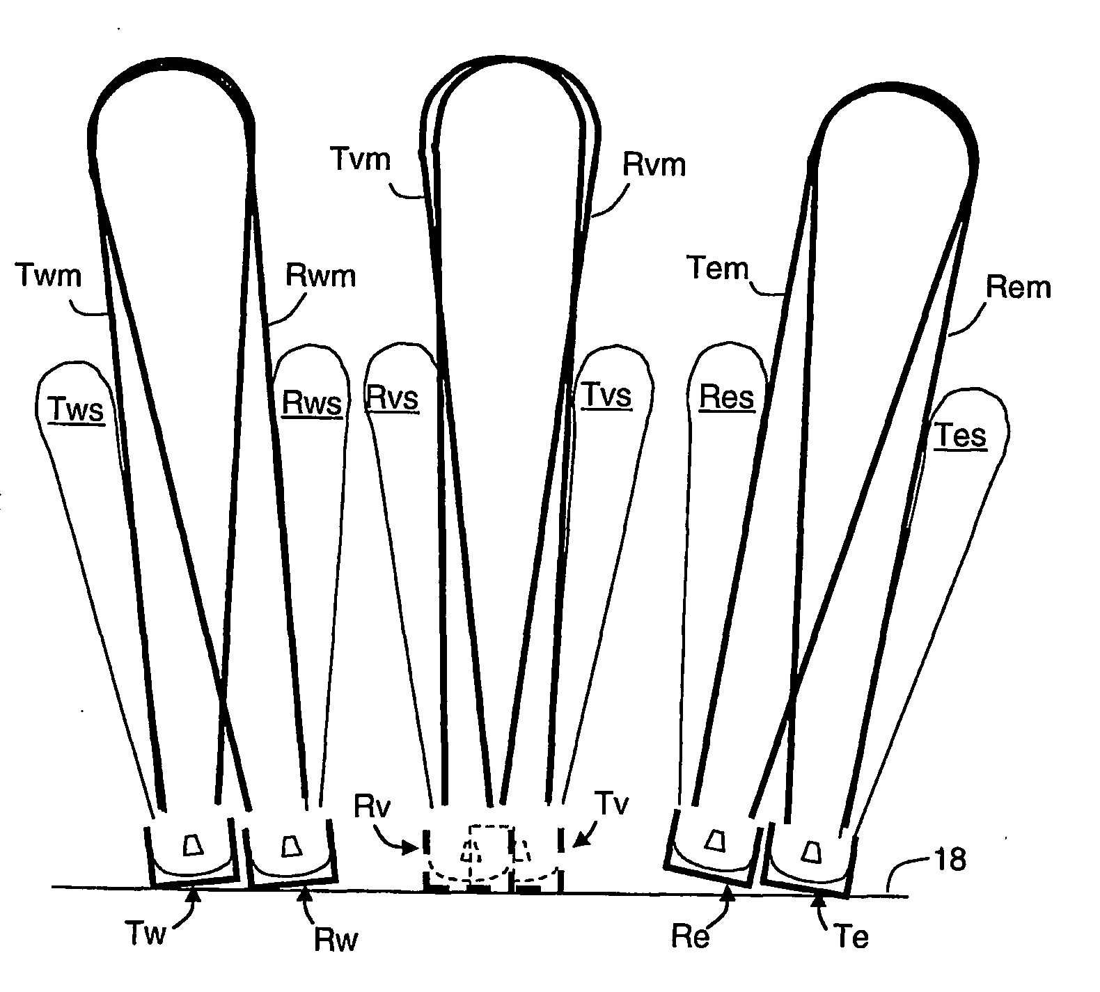
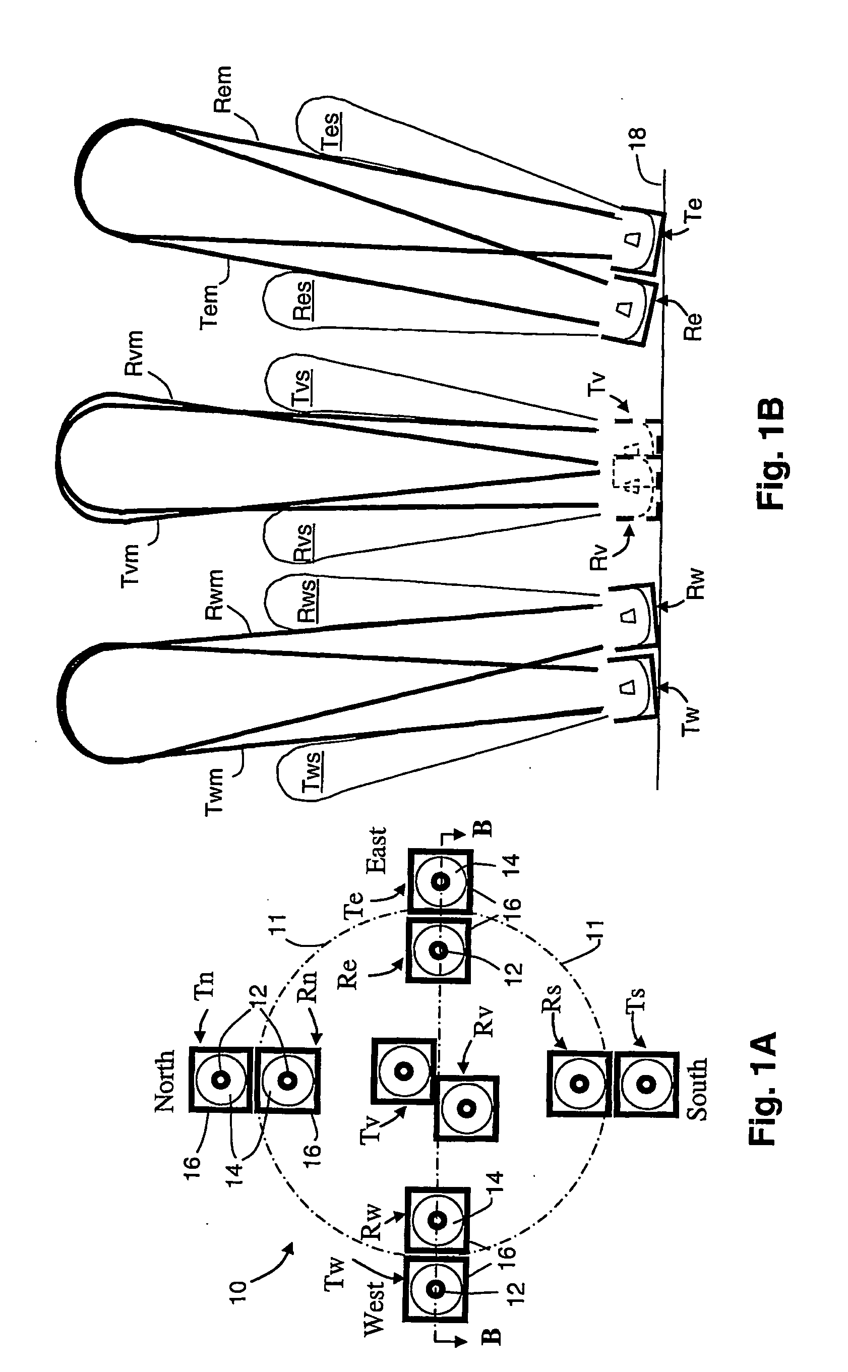
[0020]It is highly desirable that the transmitter and receiver of each pair has its own separate reflector dish and that the two dishes of the pair are spaced some distance apart and are acoustically insulated—preferably by surrounding baffles—from one another to (i) create the desired main antenna lobe in conjunction with the acoustic transducer and (ii) effectively attenuate the direct signal transmission between the respective transmitter and receiver. This will also ensure that the direct signal from each of the other transmitters of the array is also significantly attenuated before detection by each receiver.
[0021]The transmitter-receiver pairs of the array may be activated individually and in turn, or altogether at once, or in combinations of two or more at the same time. While one-at-a-time operation has the advantage that no direct or echo signal generated by any other transmitter can be detected by the sole active receiver, it will increase the system cycle time by a factor of five. We have found that simultaneous activation of all transmitters and receivers is quite feasible provided adequate passive attenuation of direct signals, confinement of transmit and receive beams and spread of pointing angles are ensured. While wider pointing angle spread reduces the likelihood that echoes from one transmitter will be detected by receivers other than its pair, they also lead to loss of system accuracy because the receivers will be pointing to widely separated parts of the sky. It is thus preferable from the standpoint of system coherence to have the pointing angles of all transmitters and receivers tightly bunched—ie, lying within a cone of a few degrees—and to take whatever measures that are practical to reduce interference by direct signals and undesired echoes. The optimum cone angle will vary according to the range and purpose of the system, the cone angle generally varying inversely with range. Relatively large cone angles—say over 10 degrees—will generally be inappropriate for long range systems as the different receivers of an array might well interrogate portions of the sky hundreds of meters removed from one another.

Problems solved by technology

However, issues relating to chirp time-duration appear to be unchanged from those discussed in our prior patent applications.
It is undesirable, we have found, to go much below 0.04.
This forms a lower practical limit of chirp bandwidth.

Method used


Image

  • Sodar sounding of the lower atmoshere
  • Sodar sounding of the lower atmoshere
  • Sodar sounding of the lower atmoshere

Examples


Embodiment Construction

OF THE INVENTION

[0023]Having portrayed the nature of the present invention, a particular example will now be described with reference to the accompanying drawings. However, those skilled in the art will appreciate that many variations and modifications can be made to the chosen example while conforming to the scope of the invention as defined in the following claims.

BRIEF SUMMARY OF THE DRAWINGS

[0024]In the accompanying drawings:

[0025]FIG. 1A is a diagrammatic plan view showing an array of five transmitter-receiver pairs that form the atmospheric acoustic sounder of the first example, FIG. 1B being a diagrammatic side elevation of the array taken through center line B-B of FIG. 1A. FIGS. 1A and 1B are not drawn to scale.

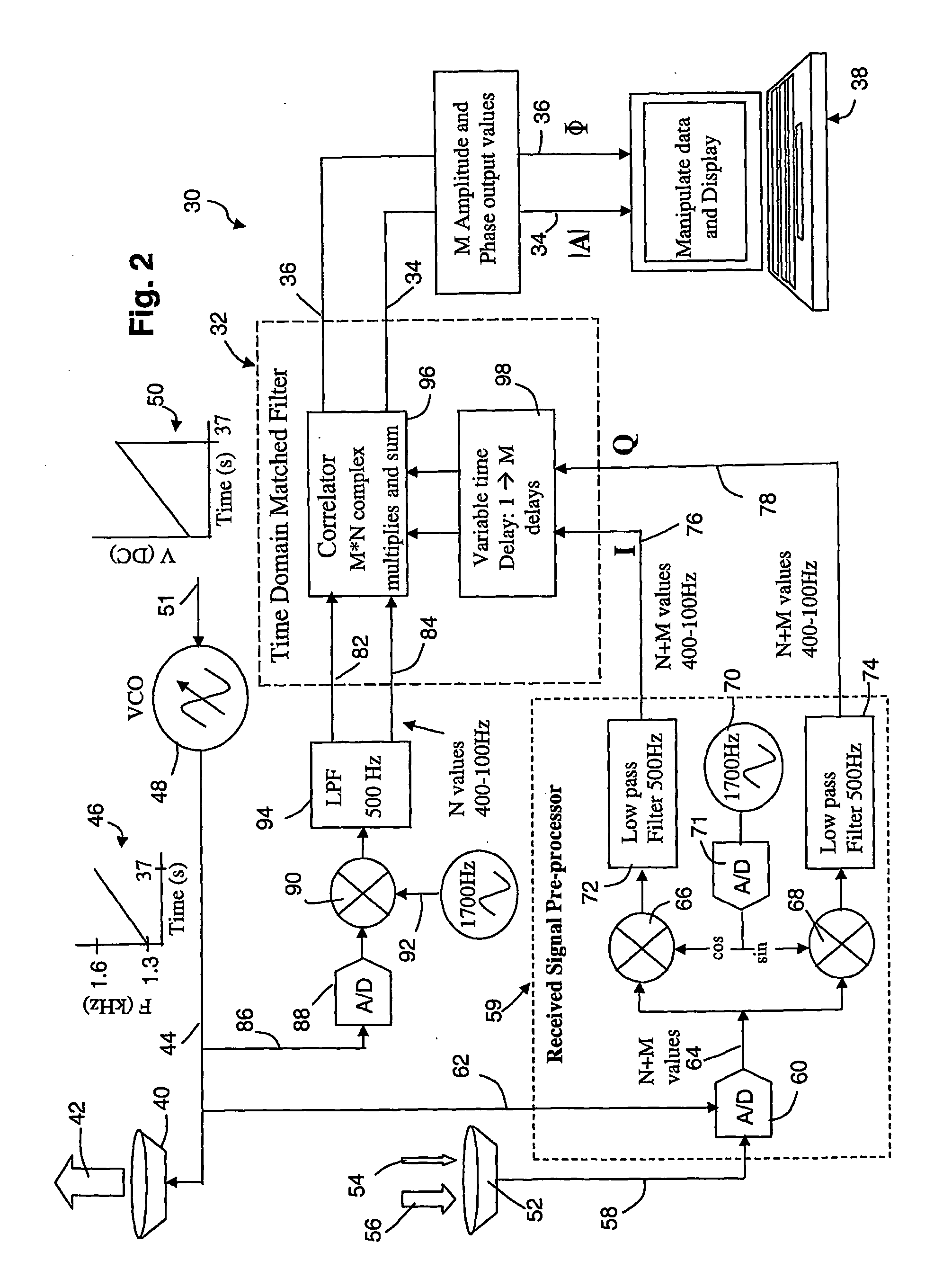
[0026]FIG. 2 is a block diagram of a time-domain matched filter signal processing system comprising the first example of a system suitable for use with the vertical transmitter-receiver pair of the array of FIGS. 1A and 1B and a linear FM chirp.

[0027]FIG. 3 is a seri...


PUM


Abstract

A monstatic sodar system using long chirps and send-while-listening techniques employs transmitter-receiver pairs (Tw, Rw; Tv, Rv; Te, Re) that have coincident main lobes (Twm, Rwm; Tvm, Rvm; Tem, Rem). The system uses digital time domain matched filters and frequency modulated or digitally modulated (eg, BPSK) chirps. Digital frequency domain matched filtering may also be used. The matched filters generate sample streams indicative of the phase and amplitude of echo signals returned from the atmosphere after the transmission of a chirp into the atmosphere.

Description

RELATED APPLICATIONS[0001]This application claims priority from Australian provisional patent application Nos. 2005903236 and 2005903353 filed on 20 Jun. 2005 and 23 Jun. 2005, respectively.BACKGROUND TO THE INVENTION[0002]1. Technical Field[0003]This invention relates to sodar methods and apparatus for sounding in the lower atmosphere and is particularly applicable to ‘monostatic’ systems where backscattered echoes are detected by receiver(s) located near the transmitter. However, in some embodiments, this invention is also applicable to ‘bistatic’ systems where forward-scattered echoes are detected by receiver(s) located remotely from the transmitter (the distances being relative to the sounding range).[0004]It is appreciated that a more narrow usage of the terms monostatic and bistatic can be found in the art in which ‘monostatic’ indicates systems in which the same aerial is used for transmission and reception (as is common in radar) and ‘bistatic’ being used for systems where t...

Claims


Application Information

Patent Timeline
Patent Type & Authority Applications(United States)
IPC IPC(8): G01S15/88
CPCG01S15/104G01S15/325G01S15/885G01S15/586G01S15/87G01S15/34
Inventor MARTIN, ANDREW LOUIS
Owner WINDBIDCO
Why Eureka
Try Eureka