
Fastening device

a technology of fastening device and touch plate, which is applied in the direction of lightening support device, screws, building scaffolds, etc., can solve the problems of difficulty in detachment of touch plate, touch plate may not be adjusted, electronic devices with incorrectly attached touch plate may not normally work, etc., to improve assembly/disassembly convenience, increase the effect of fastening strength

Active Publication Date: 2010-02-25
TCL CHINA STAR OPTOELECTRONICS TECH CO LTD
View PDF8 Cites 13 Cited by
  • Summary
  • Abstract
  • Description
  • Claims
  • Application Information

AI Technical Summary

Benefits of technology

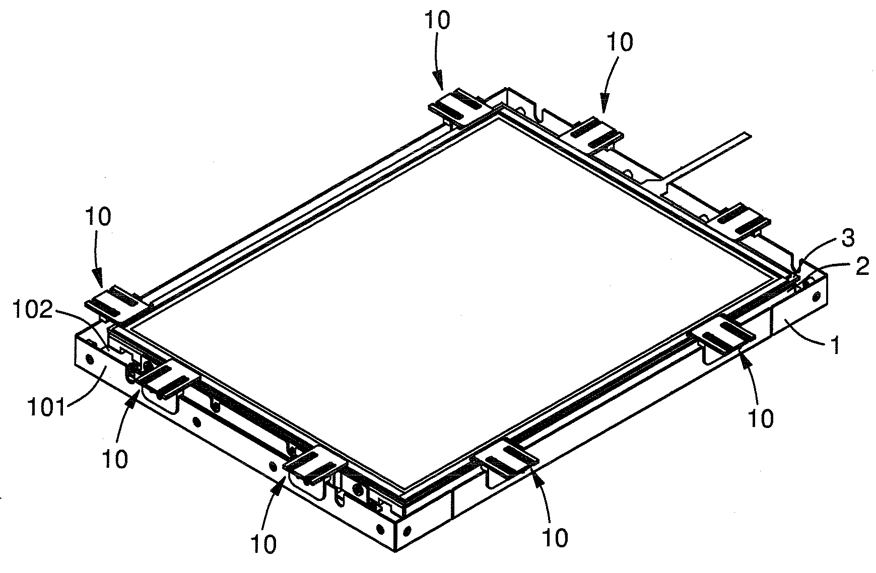
The invention is a fastening device that improves fastening strength, lowers manufacture cost, increases assembly / disassembly convenience, and improves versatility for various products with different specifications. The device includes a positioning component, a fixed plate, and a pressing plate that can be adjusted to stably and efficiently fasten articles in a carrier. The device also includes a retaining plate that prevents the article from moving along a first direction. The fastening device can be used in a liquid crystal display (LCD) where the LCD module and touch plate can be stably, efficiently, and adjustably fastened in a carrier housing. The technical effects of the invention include improved fastening strength, lower manufacture cost, increased assembly / disassembly convenience, and improved versatility for various products.

Problems solved by technology

(1) Fastened by adhering: A touch plate is firstly positioned on a specific fixture and located at a target position of a LCD. Then, the touch plate is attached to the target position by adhesive or tape. The method is useful for various touch plates of different sizes and provides a high fastening strength. However, there are still some disadvantages in the method. For example, it is difficult to detach the touch plate from the LCD after being attached. The method only may be carried out by using the specific fixture to position the touch plate. Furthermore, if the attachment of the touch plate is incorrect, the touch plate may not be adjusted again. In other words, an electronic device having the incorrect attached touch plate may not normally work.
(2) Fastened by a plastic structure: An outer frame of an electronic device has an inner surface provided with a fastening structure which is made of plastic material and specifically designed for fastening a touch plate. The method is advantageous to carry out mass production and assembly operation, while the touch plate may be easily disassembled. However, the method is unsuitably applied to an electronic device having an open type display. Meanwhile, it is necessary to design different fastening structures for various touch plates having different sizes. In other words, the fastening structure only may provide a lower universality, and disadvantageous to decrease the manufacture cost of the electronic device.
(3) Fastened by a metal pressing member: A touch plate is fastened on an electronic device by using a metal pressing member having a bent portion of 90 degrees. The pressing member includes a fixed plate, a pressing plate and a retaining plate, wherein the pressing plate is vertically extended from the fixed plate, the retaining plate is vertically formed on the pressing plate by punching, and the retaining plate is parallel to the fixed plate. In assembly, the fixed plate is fixed on a side wall of the electronic device, the pressing plate abuts against a surface of the touch plate, and the retaining plate abuts against an edge of the touch plate. Thus, the touch plate may be fastened on the electronic device based on three dimensional directions. The method is advantageous to carry out assembly operation and disassembly operation, and provide a high fastening strength. However, the metal pressing member is an integrated one-piece metal sheet, wherein the distance between the retaining plate and the fixed plate is fixed and may not be adjusted. As a result, the metal pressing member only may be applied to the electronic device which has a fixed distance between the edge of the touch plate and the side wall of the electronic device. If the distance between the edge of the touch plate and the side wall of the electronic device is varied, it is necessary to manufacture another specific pressing member with different size. Therefore, the method only may provide a lower universality, and may not be applied to touch plates with various specifications.

Method used


Image

  • Fastening device
  • Fastening device
  • Fastening device

Examples


Embodiment Construction

[0024]In the following detailed description of the preferred embodiments, reference is made to the accompanying drawings which form a part hereof, and in which shown by way of illustration specific embodiments in which the invention may be practiced. In this regard, directional terminology, such as “top,”“bottom,”“front,”“back,” etc., is used with reference to the orientation of the Figure(s) being described. The components of the present invention may be positioned in a number of different orientations. As such, the directional terminology is used for purposes of illustration and is in no way limiting. On the other hand, the drawings are only schematic and the sizes of components may be exaggerated for clarity. It is to be understood that other embodiments may be utilized and structural changes may be made without departing from the scope of the present invention. Also, it is to be understood that the phraseology and terminology used herein are for the purpose of description and sh...


PUM

PropertyMeasurementUnit
distanceaaaaaaaaaa
reaction speedaaaaaaaaaa
sizesaaaaaaaaaa

Abstract

A fastening device is provided for fastening at least one article on a carrier. The fastening device includes at least one positioning component, a fixed plate fixed on the carrier, and a pressing plate positioned on the fixed plate by the positioning component. The pressing plate has at least one positioned portion and a retaining plate corresponding to the fixed plate. The retaining plate abuts against a side edge of the article for preventing the article from moving along a first direction. The positioning component movably passes through the positioned portion to allow the pressing plate to selectively move along the first direction and be positioned on the fixed plate for adjusting the distance between the retaining plate and the fixed plate.

Description

CLAIM OF PRIORITY[0001]This application claims priority to Taiwanese Patent No. 097131626 filed on Aug. 19, 2008.BACKGROUND OF THE INVENTION[0002]1. Field of the Invention[0003]The invention relates to a fastening device, and more particularly to a fastening device for fastening at least one article in a carrier. The invention also relates to a liquid crystal display having a fastening device.[0004]2. Description of Related Art[0005]Recently, with the development of technologies, liquid crystal displays (LCD) have been applied to various fields. Nowadays, the trend of LCD technologies is to provide a touch plate on a LCD for providing an inputting means. Since the application of the touch plate is gradually widespread day by day, the touch plate has become an essential inputting means of various electronic apparatuses, such as computers, PDAs (personal digital assistants), and mobile phones. The application of the touch plate may provide advantages of high reaction speed, less occup...

Claims


Application Information

Patent Timeline
Patent Type & Authority Applications(United States)
IPC IPC(8): G02F1/1333F16B39/00
CPCF16B5/0642G06F1/1605F16B5/0664
Inventor YUAN, JIEDAI, GONG-YI
Owner TCL CHINA STAR OPTOELECTRONICS TECH CO LTD
Learn More