Power board, on-board connector, lighting device, display device and television receiver

a technology for on-board connectors and television receivers, which is applied in the direction of coupling device connections, electrical apparatus casings/cabinets/drawers, instruments, etc., can solve the problem that reflow soldering cannot be applied to circuit boards formed of materials, and achieve the effect of preventing the connection between the terminals, reducing and preventing the flexural rigidity of the output terminal

Inactive Publication Date: 2010-02-18
SHARP KK +1
View PDF18 Cites 4 Cited by
  • Summary
  • Abstract
  • Description
  • Claims
  • Application Information

AI Technical Summary

Benefits of technology

[0014]In this case, the relay terminal can be inserted into the engaging recess so as to be connected to the output terminal therewithin. Thereby, the connection between the terminals can be prevented from interference with foreign substances.
[0015]In the power board described above, a positioning portion, which can lock the output terminal so that displacement of the output terminal along the inside surface of the engaging recess is restricted, may be provided on the inside surface.
[0016]In this case, the displacement of the output terminal is restricted by the positioning portion, and therefore the flexural rigidity of the output terminal is not required to be increased for displacement prevention. The reduced flexural rigidity of the output terminal, thus provided, results in reduction of the frictional resistance developed when the relay terminal is connected to the output terminal. Thus, the operational efficiency at the time of connection can be improved.

Problems solved by technology

In the case that components are thus mounted to both surfaces of the circuit board, there is no choice but to use reflow soldering as a soldering method for fixing the components to the circuit board, because solder dipping that involves dipping of the circuit board in a molten solder bath cannot be applied.
However, the reflow soldering cannot be applied to a circuit board formed of a material sensitive to high temperature (e.g., a phenolic paper-base copper-clad laminated board), because a reflow oven is heated to a high temperature.

Method used


Image

  • Power board, on-board connector, lighting device, display device and television receiver
  • Power board, on-board connector, lighting device, display device and television receiver
  • Power board, on-board connector, lighting device, display device and television receiver

Examples


embodiment 1

Preferred Embodiment 1

[0080]Preferred embodiment 1 according to the present invention will be hereinafter explained with reference to FIGS. 1 to 16.

Overview of Display Device D

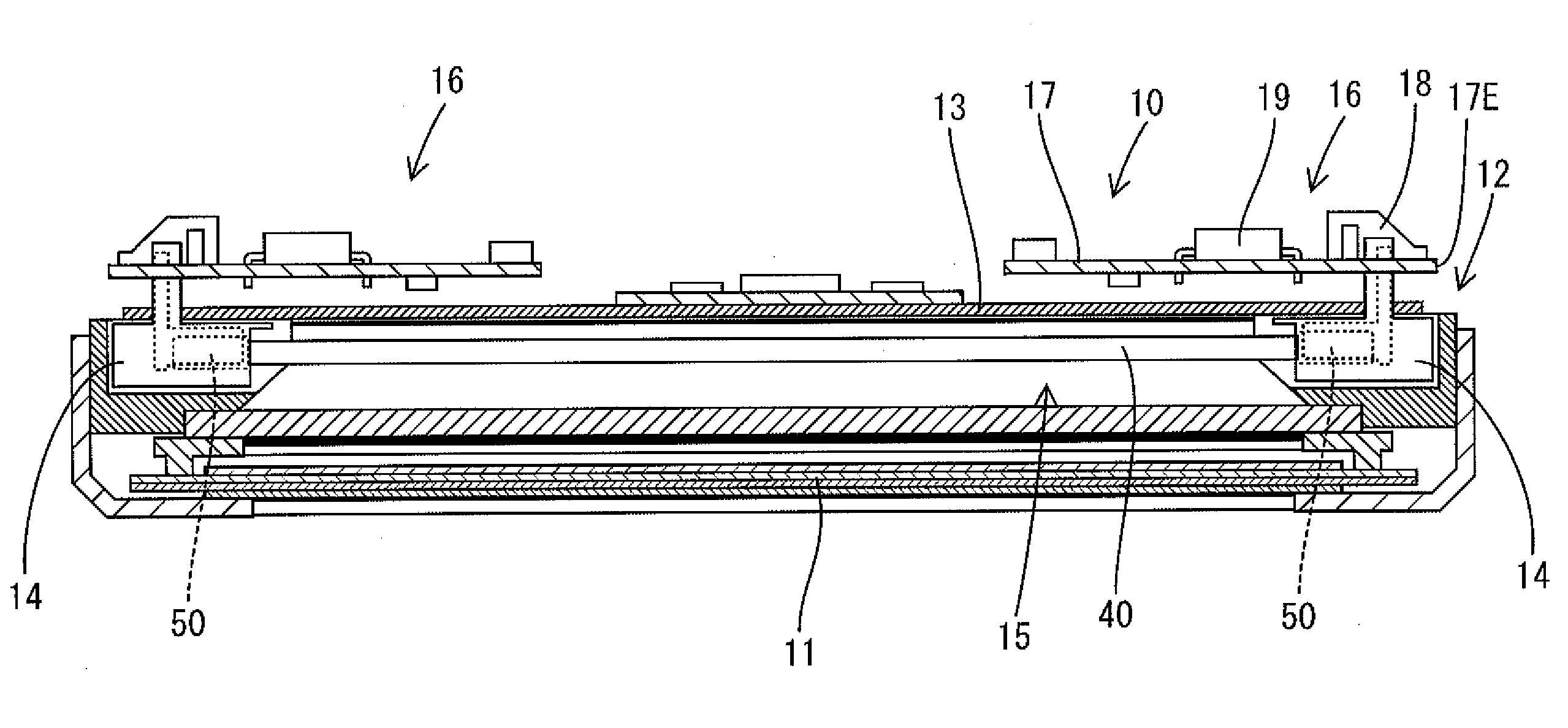
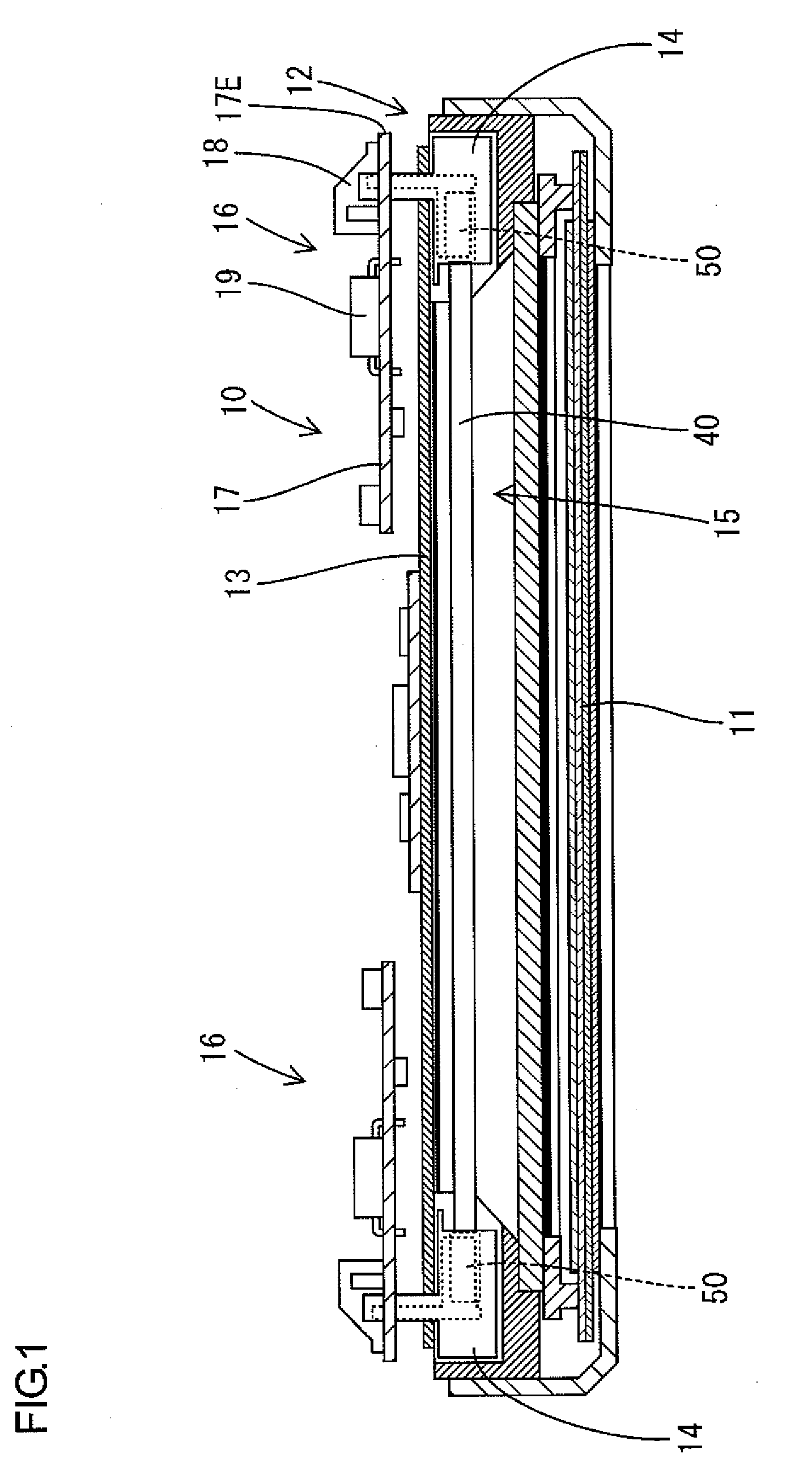
[0081]A display device D shown in FIG. 16 is a so-called liquid crystal display device including a display panel 11 and a lighting device 10 as shown in FIG. 1, which preferably has a horizontally-elongated rectangular shape as a whole. The display panel 11 is disposed on the front side of the lighting device 10, so that the lighting device 10 as a backlight can illuminate the display panel 11 from the back side. The display device D can be applied to a television receiver. As shown in FIG. 16, the television receiver includes the display device D, and front and back cabinets Ca and Cb capable of holding the display device D therebetween. Further included are a power source P other than a power board 16 described below, a tuner T and a stand S. FIG. 1 schematically shows the display device D, and therefore the...

embodiment 2

Preferred Embodiment 2

[0119]Next, preferred embodiment 2 of the present invention will be explained with reference to FIGS. 17 to 28. In the preferred embodiment 2, the construction of the lighting device 110 of a display device D differs from that of preferred embodiment 1. The other constructions are similar to preferred embodiment 1. Therefore, the same constructions are designated by the same symbols, and explanations for the constructions, operations and effects thereof are omitted.

Overview of Lighting Device 110

[0120]The lighting device 110 includes a lamp unit 112 and power boards 116, as shown in FIGS. 17 and 28. The lamp unit 112 includes a metallic chassis 113, which preferably has a horizontally-elongated rectangular plate and functions as a reflector plate. Further included are a plurality of discharge tubes 115 held in a horizontal position and vertically arranged on the front side of the chassis 113 so as to be parallel or substantially parallel to one another, and a p...

embodiment 3

Preferred Embodiment 3

[0155]Next, preferred embodiment 3 of the present invention will be explained with reference to FIGS. 29 to 35. In preferred embodiment 3, the constructions of a structure to support a discharge tube 115 differ from those of preferred embodiment 2. The other constructions are similar to preferred embodiment 2. Therefore, the same constructions are designated by the same symbols, and explanations for the constructions, operations and effects thereof are omitted.

Overview of Grounding Member 150

[0156]In preferred embodiment 2, the end portions of a discharge tube 115 are supported by relay connectors 114, each of which includes a holder 120 and a relay terminal 131. In preferred embodiment 3, as shown in FIGS. 29 and 30, one of the end portions of a discharge tube 115 is supported by the same relay connector 114 as in preferred embodiment 2, while the other end portion of the discharge tube 115 is supported by a grounding member 150.

[0157]As shown in FIG. 32, the ...


PUM

PropertyMeasurementUnit
angleaaaaaaaaaa
poweraaaaaaaaaa
insulatingaaaaaaaaaa

Abstract

In a power board, relay terminals penetrate a circuit board through fitting holes, and are connected to output terminals. The fitting holes are thus formed as through holes on the circuit board, and thereby on-board connectors provided for connection to the relay terminals on a chassis can be arranged on the back surface of the circuit board on the opposite side of the chassis. Electronic components free from restriction of the positional relationship with the chassis can be mounted on the back surface of the circuit board, as are the on-board connectors.

Description

BACKGROUND OF THE INVENTION[0001]1. Field of the Invention[0002]The present invention relates to a power board, an on-board connector, a lighting device, a display device and a television receiver.[0003]2. Description of the Related Art[0004]An example of a lighting device capable of functioning as a backlight for a liquid crystal display device is disclosed in JP-A-2004-294592. The lighting device has a construction in which relay terminals are mounted into through holes formed on a chassis that has a substantially flat plate-shaped configuration and functions as a reflector plate. An electrode portion of a discharge tube arranged on the front side of the chassis and a power board arranged on the back side of the chassis are connected to each relay connector, so that the discharge tube can receive the power supply from the power board via the relay terminal.[0005]In the power board described in JP-A-2004-294592, electronic components are mounted on the surface of a circuit board on...

Claims


Application Information

Patent Timeline
Patent Type & Authority Applications(United States)
IPC IPC(8): H04N5/64H05K5/00H01R12/00G09F13/04F21S2/00F21V23/00F21V23/06F21Y103/00G02F1/1333G02F1/13357H01R12/71H01R12/75H01R12/77
CPCG02F1/133604G02F1/133608G02F2001/133612H01R33/94H01R33/02H01R33/7642H01R12/55G02F1/133612G02F1/1335H01R12/51
Inventor TAKATA, YOSHIKIIWAMOTO, KENICHIKUDO, TAKAAKIIKENAGA, NAOFUMI
Owner SHARP KK
Why Eureka
Try Eureka