
Plug connector

a plug-in connector and connector technology, applied in the field of plug-in connectors, can solve the problems of unsteady connection between and assembly cannot transmit signals, and achieve the effect of avoiding terminals and stable connection between

Inactive Publication Date: 2009-12-08
CHENG UEI PRECISION IND CO LTD
View PDF3 Cites 12 Cited by
  • Summary
  • Abstract
  • Description
  • Claims
  • Application Information

AI Technical Summary

Benefits of technology

[0007]As described above, because both of the first and the second contacting branches of the contacts electrically are connected with the terminals, so that the connection therebetween will be stable. It avoids the terminals from disconnecting the contacts when the assembly of the receptacle and plug connector suffers from an outside force, so that the signals can be transmitted reliably between the receptacle connector and the plug connector.

Problems solved by technology

Though the connection structure between the terminals and the contacts is simple, it may cause unsteady connection between the terminals and corresponding contacts, and as a result, the terminals of the receptacle connector and the contacts of the plug connector would more likely be disconnected from each other when the assembly thereof is accidentally subject to an external force, then the assembly cannot transmit signal stably.

Method used


Image

  • Plug connector
  • Plug connector
  • Plug connector

Examples


Embodiment Construction

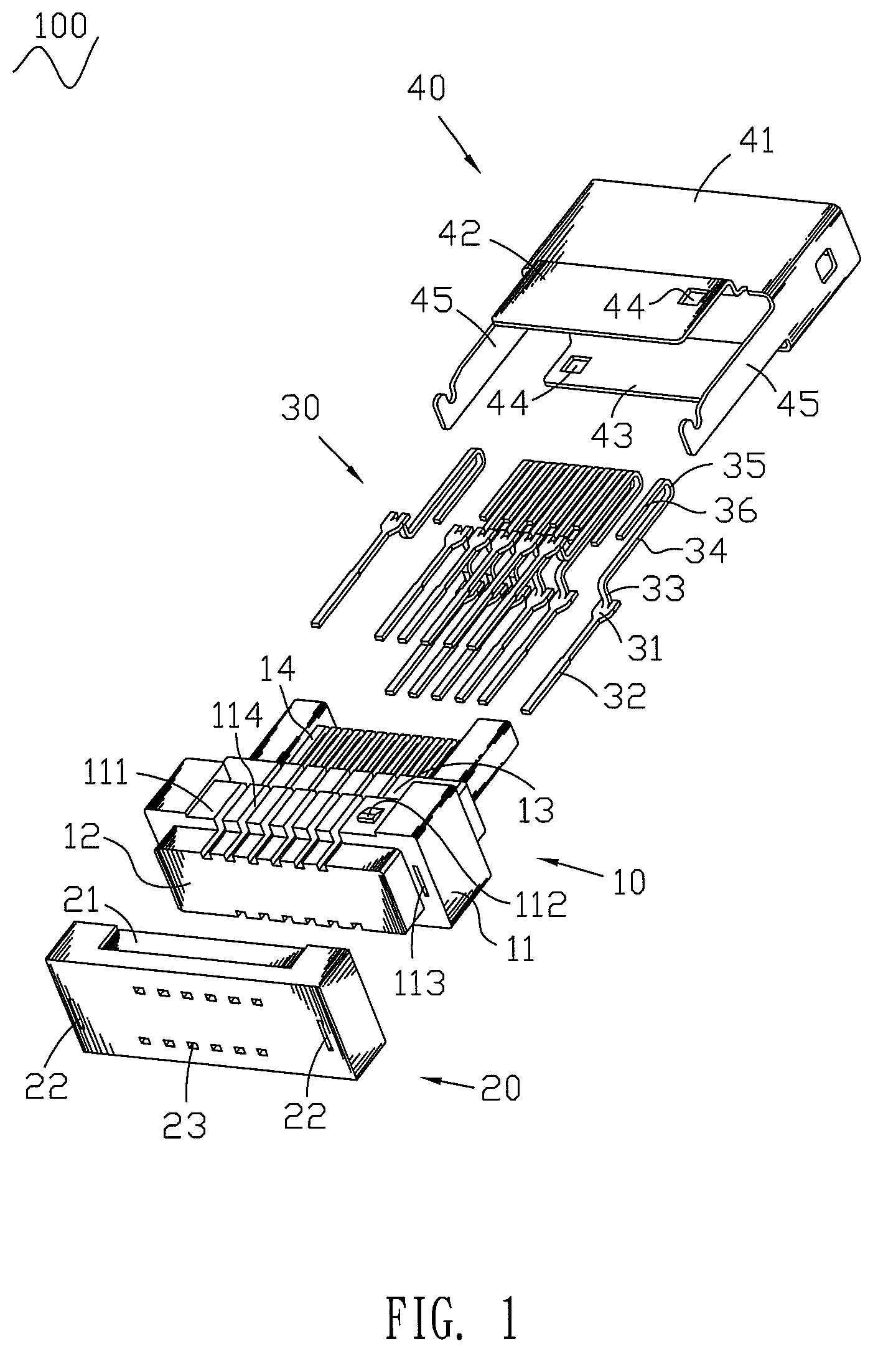
[0013]Please Refer to FIG. 1, a plug connector 100 according to the invention includes an insulating housing 10, a cover 20, a plurality of contacts 30 and a shell 40.

[0014]The insulating housing 10 has a substantially rectangular base body 11. The base body 11 defines a butt portion 12 protruding forward from a front surface thereof and a tongue portion 14 extending rearward from a rear surface thereof. Two guide portions 13 project rearward from the rear surface of the base body 11 with one of which located over a front position of a top surface of the tongue portion 14 and the other one located under a front position of a bottom surface of the tongue portion 14. In this case, the base body 11, the guide portions 13 and the tongue portion 14 corporately form a substantially stair-shaped structure therebetween. A top and bottom surfaces of the base body 11 respectively define an opening 111 passing therethrough and a substantially wedge-shaped lump 112 disposed in the opening 111. ...


PUM


Abstract

A plug connector includes an insulating housing and a plurality of contacts received in the insulating housing. The insulating housing has a base body and a tongue portion extending rearward from the base body. The tongue portion has a top portion and a bottom portion. Each of the contacts has a substantially U-shaped contacting portion which includes a first contacting branch, a second contacting branch substantially parallel to the first contacting branch and a connecting portion connected one end of the first and second contacting branches together. The first and the second contacting branches of the contacts are respectively exposed at the top and bottom portions of the tongue portion for both electrically contacting terminals of a complementary receptacle connector.

Description

BACKGROUND OF THE INVENTION[0001]1. Field of the Invention[0002]The present invention relates to an electrical connector, and more particularly to a plug connector having improved contacts.[0003]2. The Related Art[0004]In general, a plug connector is adapted to electrically connect with a complementary receptacle connector for transmitting signals therebetween. The plug connector includes an insulating housing and a plurality of contacts received in the insulating housing. The receptacle connector includes an insulator and a plurality of terminals disposed in the insulator. When the receptacle connector is mated with the plug connector, the terminals are electrically connected with the contacts to transmit the signals.[0005]However, the terminal of the receptacle connector contacts with only one side of the contact of the plug connector to achieve electrical connection therebetween. Though the connection structure between the terminals and the contacts is simple, it may cause unstea...

Claims


Application Information

Patent Timeline
Patent Type & Authority Patents(United States)
IPC IPC(8): H01R9/22
CPCH01R24/60H01R2107/00H01R13/6581
Inventor CHIANG, SHU-MAN
Owner CHENG UEI PRECISION IND CO LTD
Learn More