Eureka AIR delivers breakthrough ideas for toughest innovation challenges, trusted by R&D personnel around the world.

LED reading light and method for operating an LED reading light

Active Publication Date: 2010-02-18
GOODRICH LIGHTING SYST
View PDF2 Cites 21 Cited by
  • Summary
  • Abstract
  • Description
  • Claims
  • Application Information

AI Technical Summary

Benefits of technology

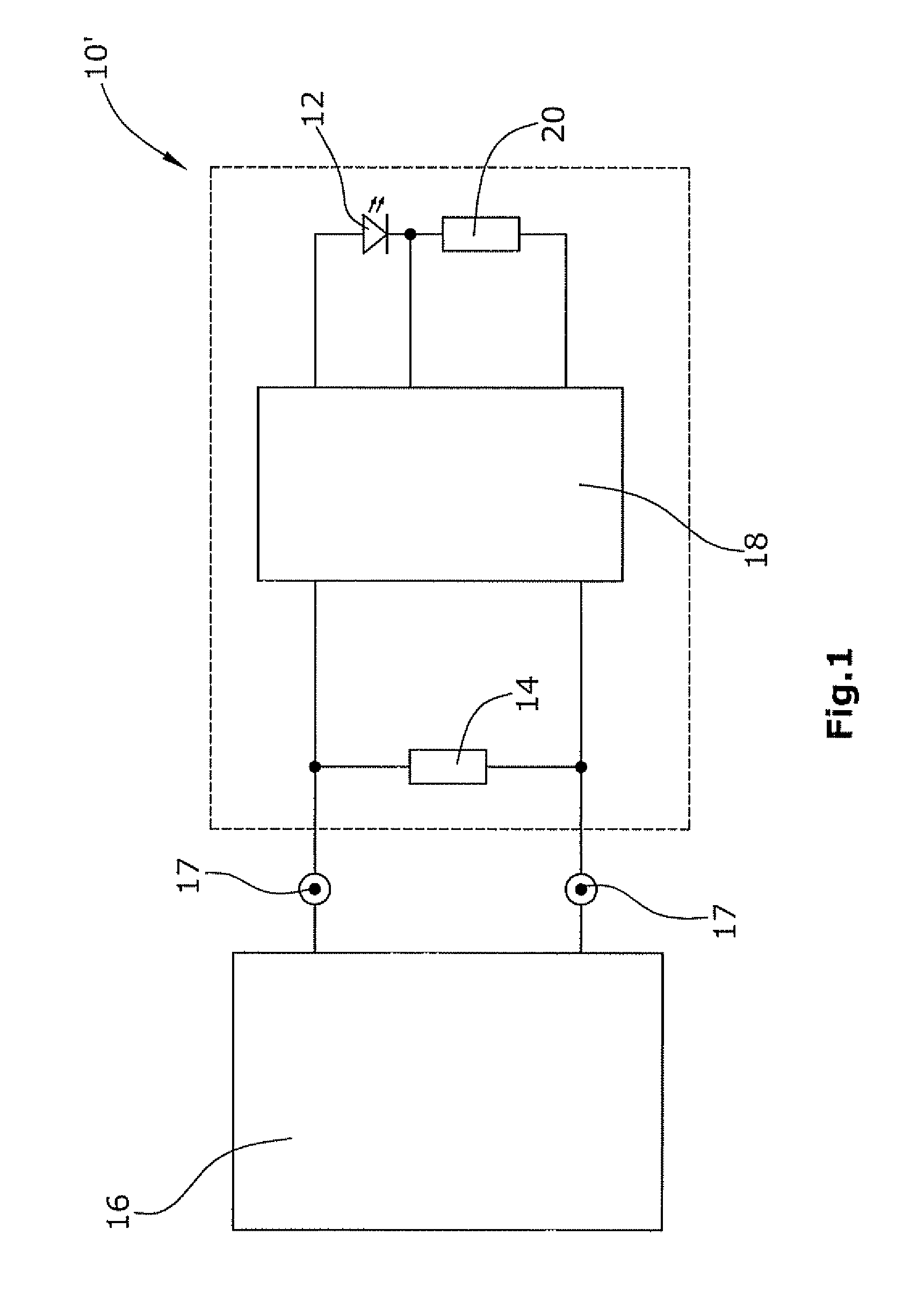
[0014]According to the invention it is therefore also proposed with the invention to no longer use primarily the passenger transportation vehicle's power supply unit for the operation of the LED light means of an LED reading light but rather a unit integrated into the LED reading light, namely a separate current controller. In so doing, the LED reading light will however continue to comprise a coding resistor, or in general an electrical coding component, which is read out in the customary manner by the supply unit installed in the passenger transportation vehicle. The special feature consists in the fact that this coding component exhibits the electrical parameter, or the electrical cha

Problems solved by technology

In so doing, the set of problems consists in, among other things, the fact that the LED light means can only be produced with a non-negligible production-related tolerance.
Both of these things make it more difficult to an increasing extent to meet the present specification requirements in effect in the civilian aerospace industry for LED light means for LED reading lights.
This however is also not possible without problems since the changeover of the power supply units means a great technological effort which the manufacturers of, in particular, civilian airplanes do not wish to take on.
Furthermore, the airlines demand that defective LED light means of reading lights can be exchanged for new LED light means without new power supply units also being required for the operation of these new LED light means.

Method used


Image

  • LED reading light and method for operating an LED reading light
  • LED reading light and method for operating an LED reading light
  • LED reading light and method for operating an LED reading light

Examples


Embodiment Construction

[0027]In FIG. 3 the circuit to be encountered at present, e.g., in airplanes, of an LED seat light / reading light is represented schematically. The LED reading light 10 comprises an LED light means 12 which is disposed in a housing with a cooling element and light pane. Connected in parallel to the LED light means 12 is a coding resistor 14 which is also a component of the LED reading light 10. In the schematic representation according to FIG. 3 the housing, the cooling element, the light pane, and other components belonging to the LED reading light are not represented since these components are not relevant to the invention.

[0028]The power supply, and in particular the constant-current supply, of the LED light means 12 is provided by a power supply unit 16 to which the power supply connections 17 of one or more reading lights 10 of the airplane are connected and to which moreover the other components disposed in a so-called PSU (passenger service unit) are also connected. The power ...


PUM


Abstract

The LED reading light, in particular for a passenger transportation vehicle such as, for example, an airplane, a bus, or a ship, is provided with two power supply connections (17) for connection to a power supply unit (16), an LED light means for giving off light with a desired light intensity, and a coding component (14), in particular a coding resistor, which is connected to at least one of the power supply connections (17), where the electrical parameter of the coding component (14) specifies the magnitude of a power supply current which can be provided for the LED light means by the power supply unit (16). Furthermore, the LED reading light is provided with a current controller (18) which is connected between the coding component (14) and the LED light means (12) and provides an operating current for the operation of the LED light means (12). The coding component (14) exhibits the electrical parameter for the provision of the maximum possible power supply current and the current controller (18) adjusts the operating current to a value at which the LED light means (12) gives off light with the desired light intensity.

Description

CROSS-REFERENCE TO RELATED APPLICATIONS[0001]This application claims priority of U.S. provisional application No. 61 / 088,747, filed Aug. 14, 2008.BACKGROUND OF THE INVENTION[0002]The invention relates to interior lighting systems for a passenger transportation vehicle such as an airplane, a bus, or a ship and, in particular an LED reading light for an airplane, bus, or similar passenger transportation vehicle.[0003]In passenger transportation vehicles, such as, for example, airplanes, buses, ships, or vehicles which run on rails (for example, railroad cars) seat lights or reading lights are used which are provided to an increasing extent with LED light means. So that the illumination is uniform, one aims to use LED light means which emit light at essentially equal intensity. In so doing, the set of problems consists in, among other things, the fact that the LED light means can only be produced with a non-negligible production-related tolerance. In the case of certain applications of...

Claims


Application Information

Patent Timeline
IPC IPC(8): H05B41/36
CPCB60Q3/0253H05B33/0845B60Q3/0259B60Q3/44B60Q3/47H05B45/10
Inventor ROEBKE, STEFFEN
Owner GOODRICH LIGHTING SYST
Why Eureka
Eureka Blog
Learn More