
Fencing system for campfire

a technology for fencing and campfires, applied in the field of fencing systems, can solve the problems of a large amount of materials, inconvenient use of conventional fences, and high cost of conventional fences, and achieve the effects of simple structure configuration, cost saving, and light weigh

Inactive Publication Date: 2010-02-18
HAZLETT BOB
View PDF21 Cites 6 Cited by
  • Summary
  • Abstract
  • Description
  • Claims
  • Application Information

AI Technical Summary

Benefits of technology

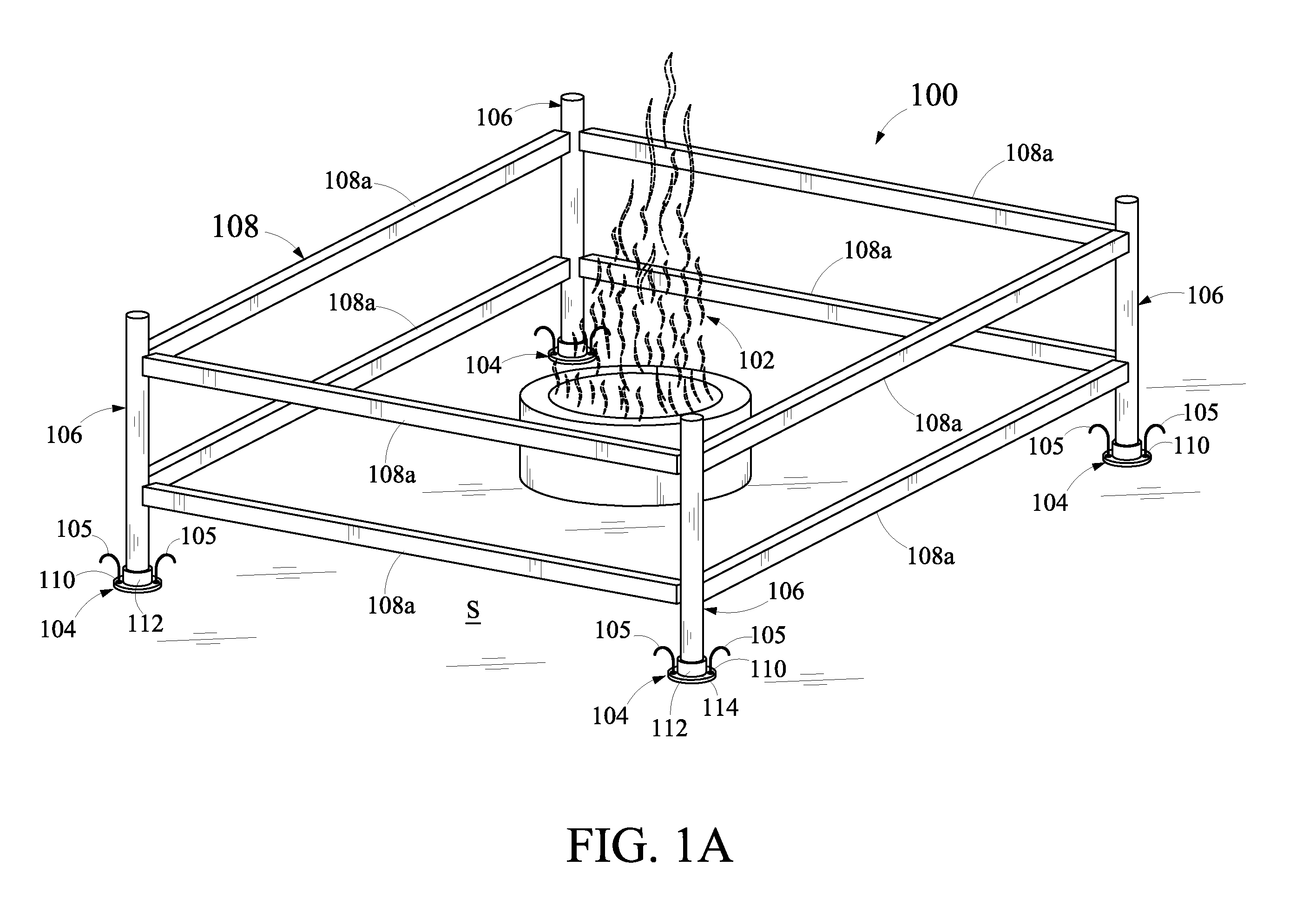
[0007]An object of the present disclosure is to provide a system for fencing a campfire, such that the system is of light weight and have a simple structural configuration.
[0009]Yet another object of the present disclosure is to provide a system for fencing a campfire that is convenient to use and is easy to set up around the campfire.
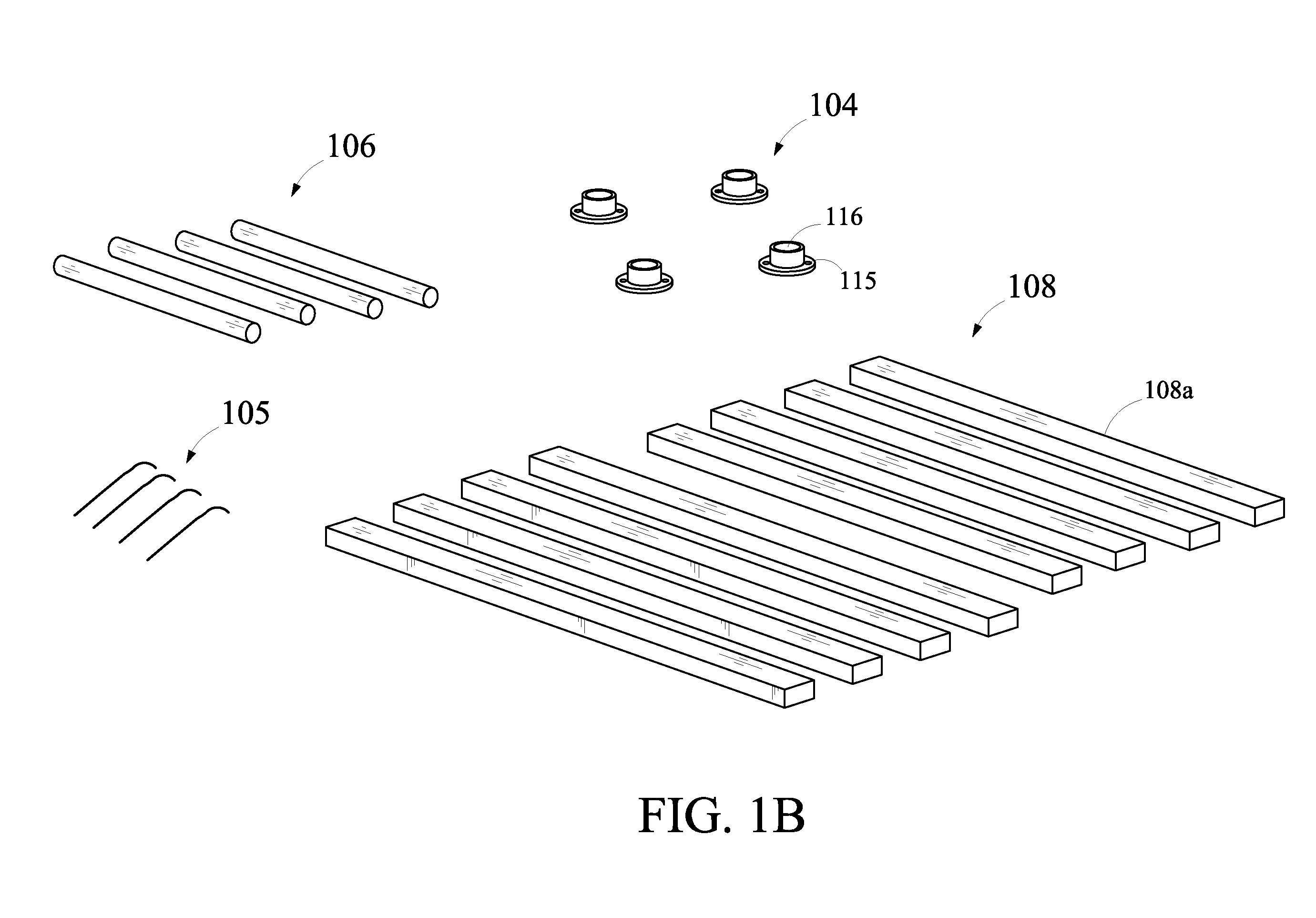
[0011]As disclosed, the fencing system includes the plurality of holding members, the plurality of posts and the plurality of fencing members. The plurality of holding member, the plurality of posts, and the plurality of fencing members are simple in structure and are made of durable material, thereby providing the fencing system that is light weight, cost effective, and simple in structural configuration. Further, such simple structural configuration of the fencing system facilitates users to conveniently set up the fencing system around the campfire. Furthermore, as the plurality of holding member, the plurality of posts, and the plurality of fencing members are removably attached with one another, the fencing system is rendered portable.

Problems solved by technology

In such occasions, the campfires may project a threat to the security of children and pets, as a child or a pet may move close to the campfires without being cognizant about the damages the campfires may cause to them.
However, the conventional fences are quite inconvenient to use due to their bulky and complex structural configuration.
Further, the conventional fences are expensive and are difficult to set up around the campfires.
Furthermore, the conventional fences are not easy to transport from one place to another due to the bulky and complex structural configuration.

Method used


Image

  • Fencing system for campfire
  • Fencing system for campfire
  • Fencing system for campfire

Examples


Embodiment Construction

[0019]For a thorough understanding of the present disclosure, reference is to be made to the following detailed description, including the appended claims, in connection with the above-described drawings. Although the present disclosure is described in connection with exemplary embodiments, the present disclosure is not intended to be limited to the specific forms set forth herein. It is understood that various omissions and substitutions of equivalents are contemplated as circumstances may suggest or render expedient, but these are intended to cover the application or implementation without departing from the spirit or scope of the claims of the present disclosure. Also, it is to be understood that the phraseology and terminology used herein is for the purpose of description and should not be regarded as limiting. The use of “including,”“comprising,” or “having” and variations thereof herein is meant to encompass the items listed thereafter and equivalents thereof as well as additi...


PUM


Abstract

A fencing system for a campfire includes a plurality of holding members, a plurality of posts and a plurality of fencing members. Each holding member of the plurality of holding members includes a base member and a lip extending upwardly from a portion of the base member defining a cavity between the base member and the lip. The plurality of holding members is adapted to be placed on a surface around the campfire. Further, each post of the plurality of posts is adapted to be disposed vertically into the cavity of the each holding member of the plurality of holding members. Furthermore, each fencing member of the plurality of fencing members is disposed horizontally between a pair of posts of the plurality of posts and the each fencing member is removably attached to the pair of posts.

Description

CROSS REFERENCE TO RELATED APPLICATIONS[0001]The present disclosure claims priority under 35 United States Code, Section 119 on the U.S. Provisional Patent Application No. 61 / 088,462 filed on Aug. 13, 2008 the disclosure of which is incorporated by reference.FIELD OF THE DISCLOSURE[0002]The present disclosure generally relates to fencing systems, and more particularly to a fencing system for a campfire.BACKGROUND OF THE DISCLOSURE[0003]Occasions such as parties, get-togethers, vacations, and other social gatherings are typically inseparable parts of peoples' lives. These occasions are generally equipped with campfires, which are enjoyed by attendees at these occasions. In such occasions, the campfires may project a threat to the security of children and pets, as a child or a pet may move close to the campfires without being cognizant about the damages the campfires may cause to them.[0004]To keep children and pets away from the campfires, people have been using conventional fences a...

Claims


Application Information

Patent Timeline
Patent Type & Authority Applications(United States)
IPC IPC(8): E04H17/14
CPCE04H12/2215E04H12/2269E04H2017/1452E04H17/161E04H17/1413E04H17/1452
Inventor HAZLETT, BOB
Owner HAZLETT BOB
Learn More